KEY ADVANTAGES
This instruction has been prepared for the correct and safe installation of wide tolerance Wall Couplings designed to ensure leak-proof and secure passage of pipelines through concrete walls, structures, and civil elements.
2.1 Fixing Before Concreting
2.2 Protection Measures
2.3 Concrete Pouring & Vibration
2.4 Formwork Removal & Cleaning
|
No |
Component Name |
Material and Technical Details |
|---|---|---|
|
1 |
Wall Penetration Pipe |
ST 37 Carbon Steel. High-strength structural body. |
|
2 |
End Rings |
Ductile Iron (GGG40/50) / ST 37 Steel. Pressure end caps applying force to the gasket. |
|
3 |
Flanges |
ST 37 Steel. Compatible with various flange standards |
|
4 |
Tee Bolts/Bolts |
Zinc-Coated Grade 8.8 Steel / AISI 304 / 316 Stainless Steel. High corrosion resistance. |
|
5 |
Conical Gasket |
EPDM / NBR. Pressure-responsive sealing technology. |
|
6 |
Nuts and Washers |
Zinc-Coated Grade 8.8 Steel / AISI 304 / 316 Stainless Steel. Secure locking system. |
|
7 |
Coating |
Epoxy / Thermoplastic. Long-lasting protection and durability. |
| COUPLİNG SIDE | FLANGE SIDE | ||||||||
|---|---|---|---|---|---|---|---|---|---|
| REFERENCE DIAMETER (mm) | APP CODE | COMPATIBLE PIPE TYPES (mm) | FLANGE SIZE (mm.) | PN10 | PN16 | PN16 | |||
| BOLT | BOLT | BOLT | |||||||
| SIZE | QUANTITY | SIZE | QUANTITY | SIZE | QUANTITY | ||||
| 50 | APP 50 | 50 Steel, 63 HDPE, 63 PVC | 50 | M16 | 4 | M16 | 4 | M16 | 4 |
| 80 | APP 80/1 | 80 AÇB (PN 10), 80 Steel, 90 PVC, 90 HDPE, 80 Ductile, 80 CI | 80 | M16 | 8 | M16 | 8 | M16 | 8 |
| APP 80/2 | 80 AÇB (PN 10), 110 PVC, 110 HDPE | ||||||||
| 100 | APP 100 | 110 PVC, 110 HDPE, 100 AÇB (PN 10), 100 CI, 100 Steel, 100 Ductile | 100 | M16 | 8 | M16 | 8 | M20 | 8 |
| 125 | APP 125 | 125 AÇB (PN 10), 140 PVC, 140 HDPE, 125 Steel, 125 CI, 125 Ductile | 125 | M16 | 8 | M16 | 8 | M24 | 8 |
| 150 | APP 150/1 | 160 PVC, 160 HDPE, 150 Steel | 150 | M20 | 8 | M20 | 8 | M24 | 8 |
| APP 150/2 | 160 PVC, 160 HDPE, 180 PVC, 180 HDPE, 150 Steel, 150 CI, 150 Ductile, 150 AÇB (PN 10) | ||||||||
| APP 150/3 | 150 AÇB (PN 12,5), PN12,5, 200 HDPE, 200 PVC | ||||||||
| 175 | APP 175 | 175 AÇB (PN 10), 200 Steel | |||||||
| 200 | APP 200/1 | 225 PVC, 225 HDPE, 200 Steel, 200 Ductile | 200 | M20 | 8 | M20 | 12 | M24 | 12 |
| APP 200/2 | 200 AÇB (PN10), 225 PVC, 225 HDPE, 200 Ductile, 200 CI | ||||||||
| APP 200/3 | 200 AÇB, (PN 12,5) PN 12,5, 250 PVC, 250 HDPE | ||||||||
| 250 | APP 250/1 | 250 Ductile, 250 Steel, 250 CI | 250 | M20 | 12 | M24 | 12 | M27 | 12 |
| APP 250/2 | 250 AÇB (PN 10), 280 PVC, 280 HDPE | ||||||||
| APP 250/3 | 250 AÇB (PN 12,5) | ||||||||
| 300 | APP 300/1 | 315 PVC, 315 HDPE, 300 CI, 300 Steel, 300 Ductile | 300 | M20 | 12 | M24 | 12 | M27 | 16 |
| APP 300/2 | 300 Ductile, 300 AÇB (PN 5) | ||||||||
| APP 300/3 | 300 AÇB (PN 10), 355 PVC, 355 HDPE, 350 Steel | ||||||||
| 350 | APP 350/1 | 300 AÇB (PN12,5), 350 Ductile, 350 CI, AÇB (PN 15) | 350 | M20 | 16 | M24 | 16 | M30 | 16 |
| APP 350/2 | 350 AÇB (PN 10), 400 PVC, 400 HDPE, 400 Steel | ||||||||
| 400 | APP 400/1 | 400 Ductile, 400 CI, 400 GRP | 400 | M24 | 16 | M27 | 16 | M33 | 16 |
| APP 400/2 | 400 AÇB (PN 10), 450 PVC, 450 HDPE, 450 Steel | ||||||||
| 500 | APP 500/1 | 500 Steel, 500 HDPE, 500 PVC, 450 AÇB (PN 10) | 500 | M24 | 20 | M30 | 20 | ||
| APP 500/2 | 500 Ductile, 500 CI, 500 GRP | ||||||||
| APP 500/3 | 500 AÇB (PN 10), 560 PVC, 560 HDPE | ||||||||
| 600 | APP 600/1 | 600 Steel, 500 AÇB (PN15) | 600 | M27 | 20 | M33 | 20 | ||
| APP 600/2 | 600 Ductile, 600 CI, 630 PVC, 630 HDPE, 600 GRP | ||||||||
| APP 600/3 | 600 AÇB (PN 10), 600 AÇB (PN12,5) | ||||||||
| 700 | APP 700 | AÇB, Steel, Ductile, GRP, PE, CI | 700 | M27 | 24 | M33 | 24 | ||
| 800 | APP 800 | AÇB, Steel, Ductile, GRP, PE, CI | 800 | M30 | 24 | M36 | 24 | ||
| 900 | APP 900 | AÇB, Steel, Ductile, GRP, PE, CI | 900 | M30 | 28 | M36 | 28 | ||
| 1000 | APP 1000 | AÇB, Steel, Ductile, GRP, PE, CI | 1000 | M33 | 28 | M39 | 28 | ||
| 1200 | APP 1200 | Steel, Ductile, GRP, PE | 1200 | M36 | 32 | M45 | 32 | ||
| 1400 | APP 1400 | Steel, Ductile, GRP, PE | 1400 | M39 | 36 | M45 | 36 | ||
| 1600 | APP 1600 | Steel, Ductile, GRP, PE | 1600 | M45 | 40 | M52 | 40 | ||
| 1600-3400 | APP1600-3400 | Steel, Ductile, GRP | |||||||
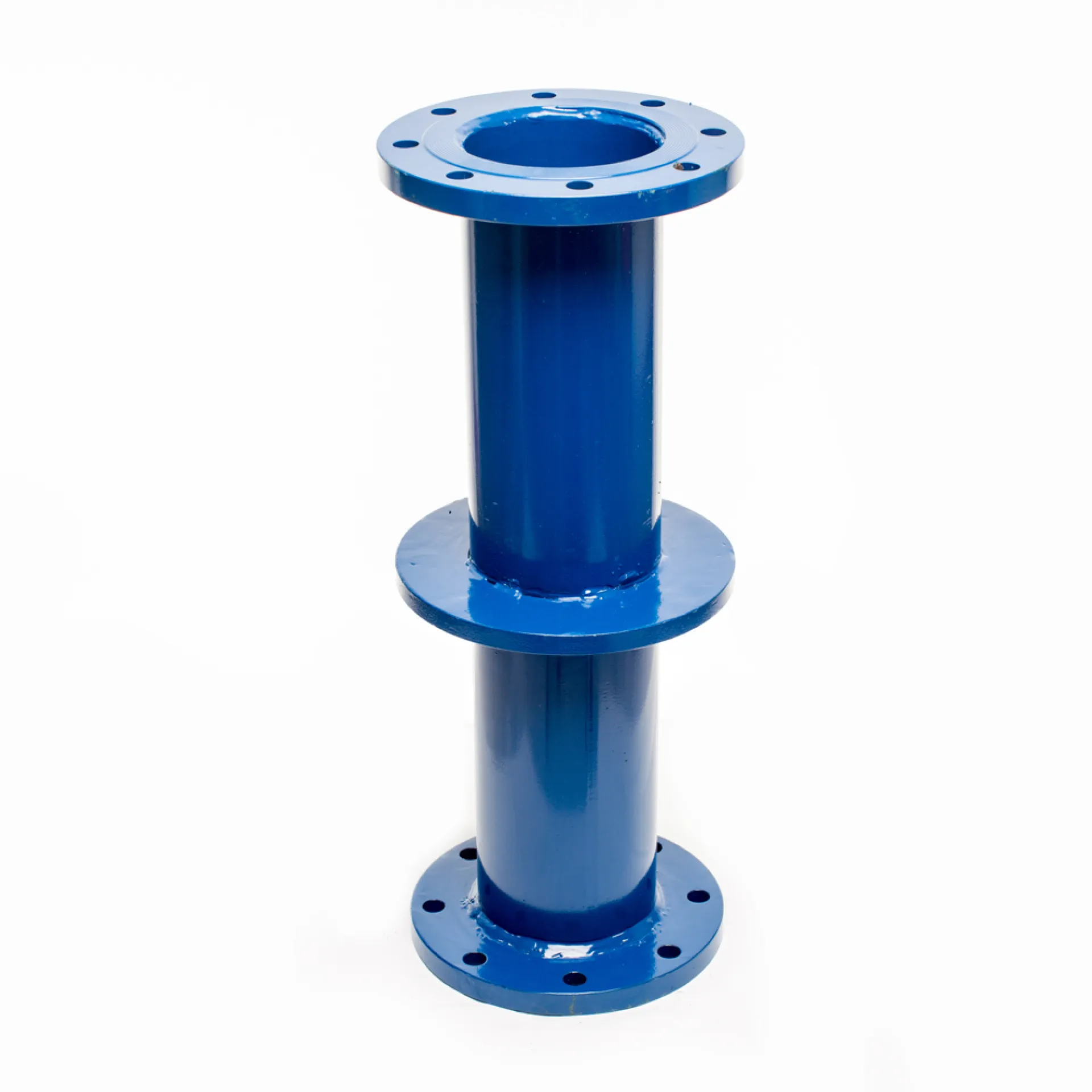
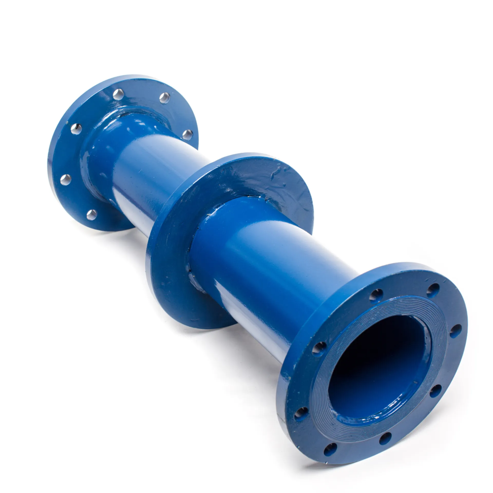
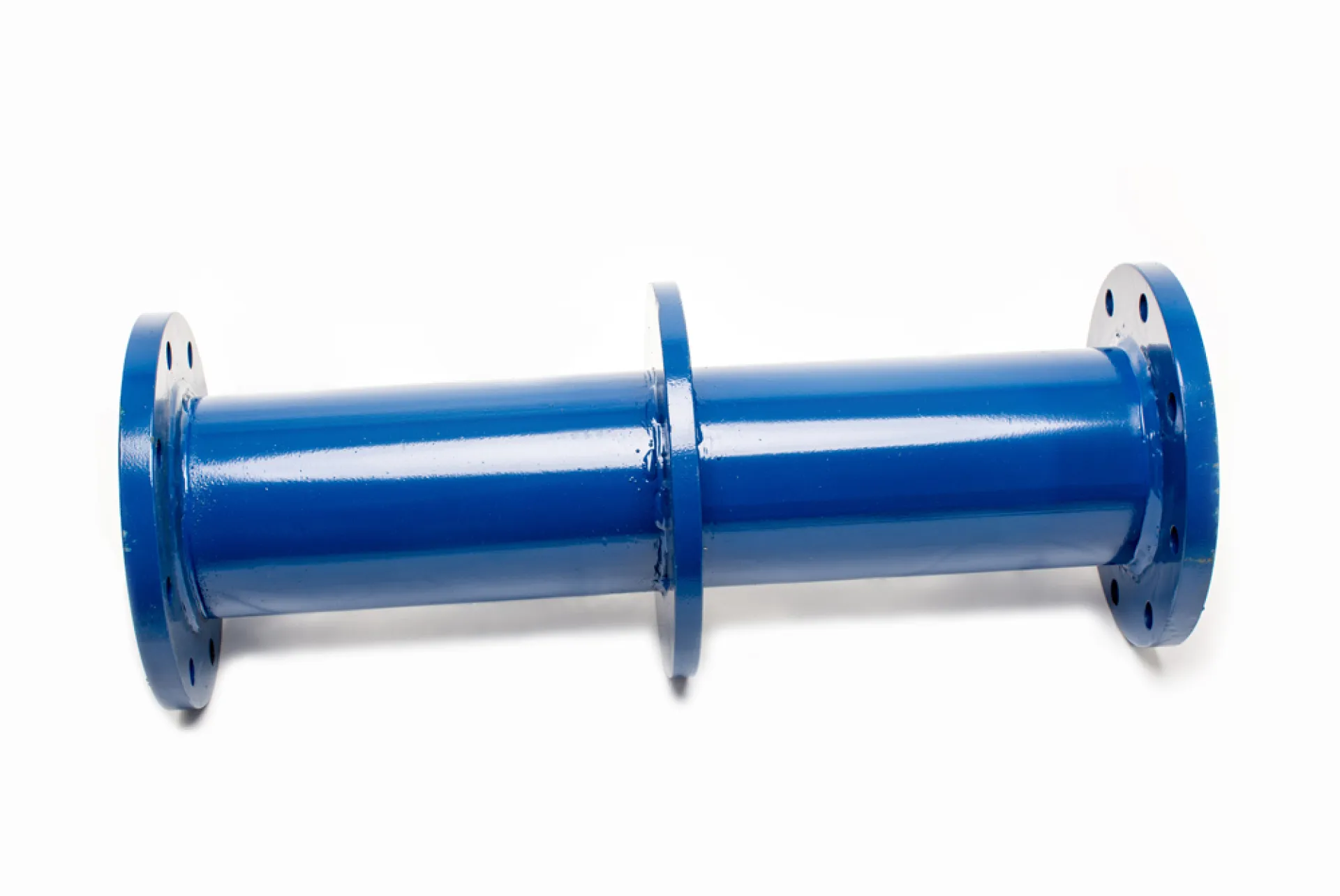
| Please specify the length and model number when ordering: | |||||||||
| 1. Model: Both ends with adapters | |||||||||
| 2. Model: One end with adapter, one end with flange | |||||||||
| 3. Model: Both ends with flanges | |||||||||
| Please specify the pressure classes of the flanges when ordering. | |||||||||
| Custom production is available for pipe diameters not listed. | |||||||||

