- Potable water transmission and distribution pipelines
- Industrial pipeline systems
- New service connection (subscriber) branching
- Service line renewal on damaged pipelines
- Air release (air valve) connection points
- Pressure gauge and instrumentation installations
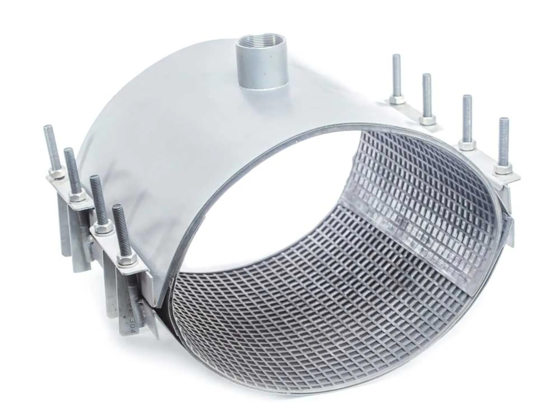
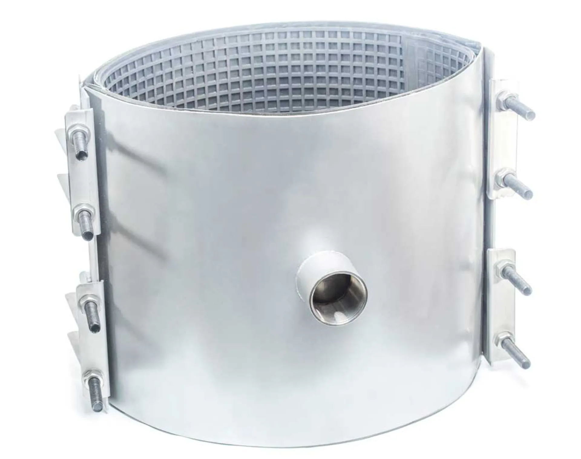
This instruction has been prepared for the correct and safe installation of tapped outlet clamps used to repair leaks, cracks, and damages in potable water, wastewater, and industrial pipelines, while simultaneously providing a threaded outlet for service connections or valve installation.
- Pre-Installation Preparation
- Correct Size Selection:
Before installation, measure the pipe outer diameter (O.D.) using a caliper or circumference tape.
Ensure that the clamp size indicated on the label is suitable for the pipe diameter.
Also verify that the outlet size matches the intended connection.
- Surface Cleaning:
Clean mud, rust, loose coating, and deposits from the pipe surface using a wire brush.
A smooth and clean surface is critical for proper sealing performance.
- Installation Steps
2.1 Lubrication
- Apply soapy water or a suitable lubricant to the pipe surface and gasket.
This allows the gasket to slide properly and prevents folding during tightening.
- Warning:
Do not use petroleum-based oils or grease, as these may damage the gasket material.
2.2 Clamp Positioning
- Preparation of the Clamp:
Loosen the nuts completely and open the clamp.
Wrap the clamp around the damaged section or the intended tapping location.
- Centering:
Ensure that the damaged area or tapping point is centered within the clamp body.
If used for repair, the clamp length should extend at least 50–100 mm beyond the damaged area on both sides.
2.3 Closing and Initial Tightening
- Bring the clamp lugs (ears) together.
- Ensure that the tapered gasket lip sits properly without folding.
- Insert the bolts into their slots and hand-tighten the nuts until snug.
2.4 Tightening Sequence
- Tighten the bolts gradually in a crosswise pattern, starting from the center and moving outward.
This ensures even compression of the gasket and proper sealing.
- Equipment Installation (Outlet Connection)
- After the clamp is fully secured on the pipe, install the valve or connection fitting onto the threaded outlet.
- Use appropriate sealing materials such as PTFE tape or sealing yarn for threaded connections.
- Final Check and Commissioning
- Waiting Period:
After installation, wait approximately 15–20 minutes and recheck the tightening torque.
The rubber gasket may settle and slightly reduce bolt tension.
- Pressure Test:
Gradually pressurize the pipeline and check for leaks.
If leakage occurs, do not overtighten the bolts—slightly loosen the clamp and reposition it before retightening.
- Important Notes
- Axial Movement:
Standard repair clamps are not designed to withstand axial loads (pull-out resistance).
If there is a risk of pipe movement, appropriate anchoring must be provided.
- Load Transfer:
Heavy valves or equipment connected to the outlet may create bending moments on the clamp.
In such cases, additional support (concrete or steel support) must be installed beneath the equipment.
- Sharp Edges:
Use protective gloves during installation to prevent injury from metal edges of the clamp.
|
No
|
Component Name
|
Material and Technical Details
|
|
1
|
Body
|
AISI 304 / 316 Stainless Steel. High corrosion resistance
|
|
2
|
Side Support Plate
|
AISI 304 / 316 Stainless Steel. Welded or integrated design
|
|
3
|
Bolt Support Rib
|
AISI 304 / 316 Stainless Steel. High-strength structure
|
|
4
|
Locking Plate
|
AISI 304 / 316 Stainless Steel. Secure locking system.
|
|
5
|
Reinforcement Plate
|
AISI 304 / 316 Stainless Steel. Prevents gasket deformation
|
|
6
|
|
|
EPDM / NBR. Pressure-responsive sealing technology
|
|
|
7
|
Bolts and Studs
|
AISI 304 / 316 Stainless Steel. Teflon-coated, high tensile strength.
|
|
8
|
Nuts and Washers
|
AISI 304 / 316 Stainless Steel. High-strength structure
|
|
9
|
Tapping Outlet Sleeve
|
AISI 304 / 316 Stainless Steel. Integrated into the body (custom diameter on request)
|
| REFERENCE DIAMETER (mm) |
APP CODE |
Operating Range (mm) |
½ “ |
¾ “ |
1 “ |
1 ¼ “ |
1 ½ “ |
1 ¾ “ |
2 “ |
| 80 |
APP-KTK/PR 80 |
95*110 |
✓ |
✓ |
|
|
|
|
|
| 90 |
APP-KTK/PR 90 |
105*115 |
✓ |
✓ |
|
|
|
|
|
| 100 |
APP-KTK/PR 100 |
115*130 |
✓ |
✓ |
✓ |
|
|
|
|
| 125 |
APP-KTK/PR 125 |
145*160 |
✓ |
✓ |
✓ |
|
|
|
|
| 150 |
APP-KTK/PR 150 |
175*190 |
✓ |
✓ |
✓ |
✓ |
|
|
|
| 175 |
APP-KTK/PR 175 |
205*215 |
✓ |
✓ |
✓ |
✓ |
|
|
|
| 200 |
APP-KTK/PR 200/1 |
215*230 |
✓ |
✓ |
✓ |
✓ |
✓ |
✓ |
✓ |
| APP-KTK/PR 200/2 |
230*243 |
✓ |
✓ |
✓ |
✓ |
✓ |
✓ |
✓ |
| APP-KTK/PR 200/3 |
240*255 |
✓ |
✓ |
✓ |
✓ |
✓ |
✓ |
✓ |
| 250 |
APP-KTK/PR 250/1 |
270*285 |
✓ |
✓ |
✓ |
✓ |
✓ |
✓ |
✓ |
| APP-KTK/PR 250/2 |
285*300 |
✓ |
✓ |
✓ |
✓ |
✓ |
✓ |
✓ |
| 300 |
APP-KTK/PR 300/1 |
320*330 |
✓ |
✓ |
✓ |
✓ |
✓ |
✓ |
✓ |
| APP-KTK/PR 300/2 |
340*355 |
✓ |
✓ |
✓ |
✓ |
✓ |
✓ |
✓ |
| 350 |
APP-KTK/PR 350/1 |
370*380 |
✓ |
✓ |
✓ |
✓ |
✓ |
✓ |
✓ |
| APP-KTK/PR 350/2 |
395*410 |
✓ |
✓ |
✓ |
✓ |
✓ |
✓ |
✓ |
| 400 |
APP-KTK/PR 400/1 |
425*435 |
✓ |
✓ |
✓ |
✓ |
✓ |
✓ |
✓ |
| APP-KTK/PR 400/2 |
450*465 |
✓ |
✓ |
✓ |
✓ |
✓ |
✓ |
✓ |
| 500 |
APP-KTK/PR 500 |
555*565 |
✓ |
✓ |
✓ |
✓ |
✓ |
✓ |
✓ |
| 600 |
APP-KTK/PR 600 |
675*685 |
✓ |
✓ |
✓ |
✓ |
✓ |
✓ |
✓ |
| Please inquire for custom production from APP-KTK 700 to APP-KTK 3400 |
| Custom production is available for pipe diameters not listed. |