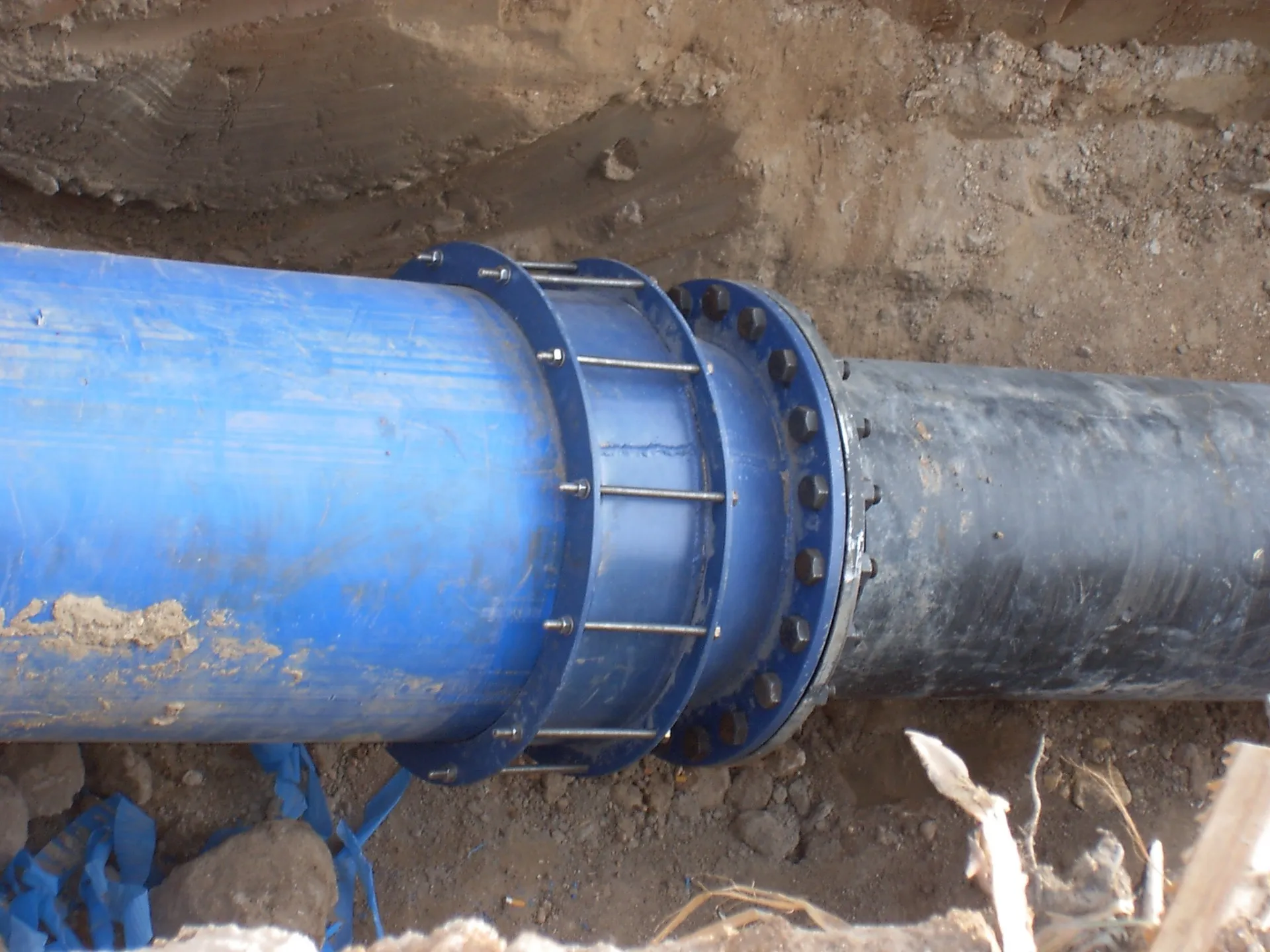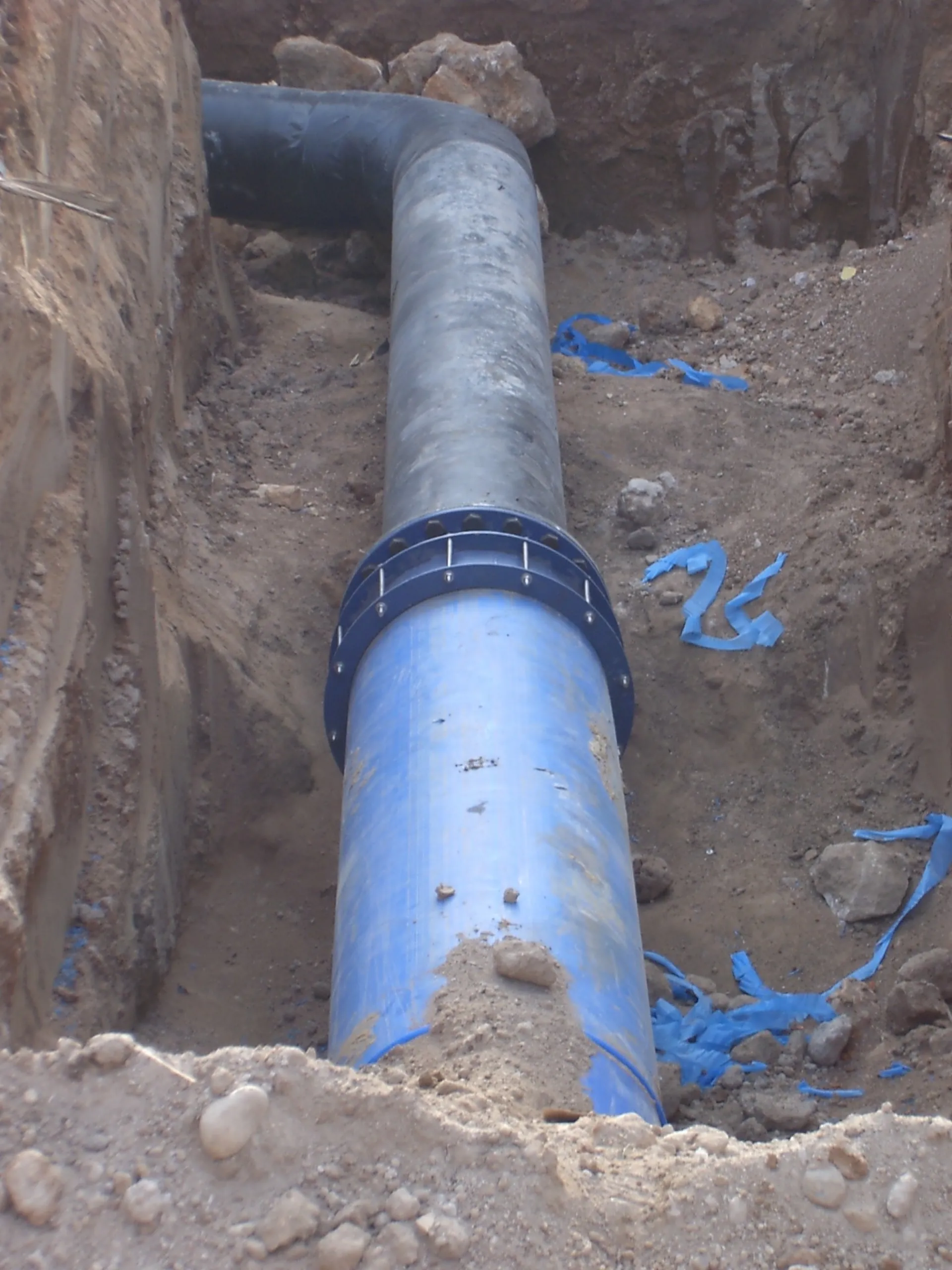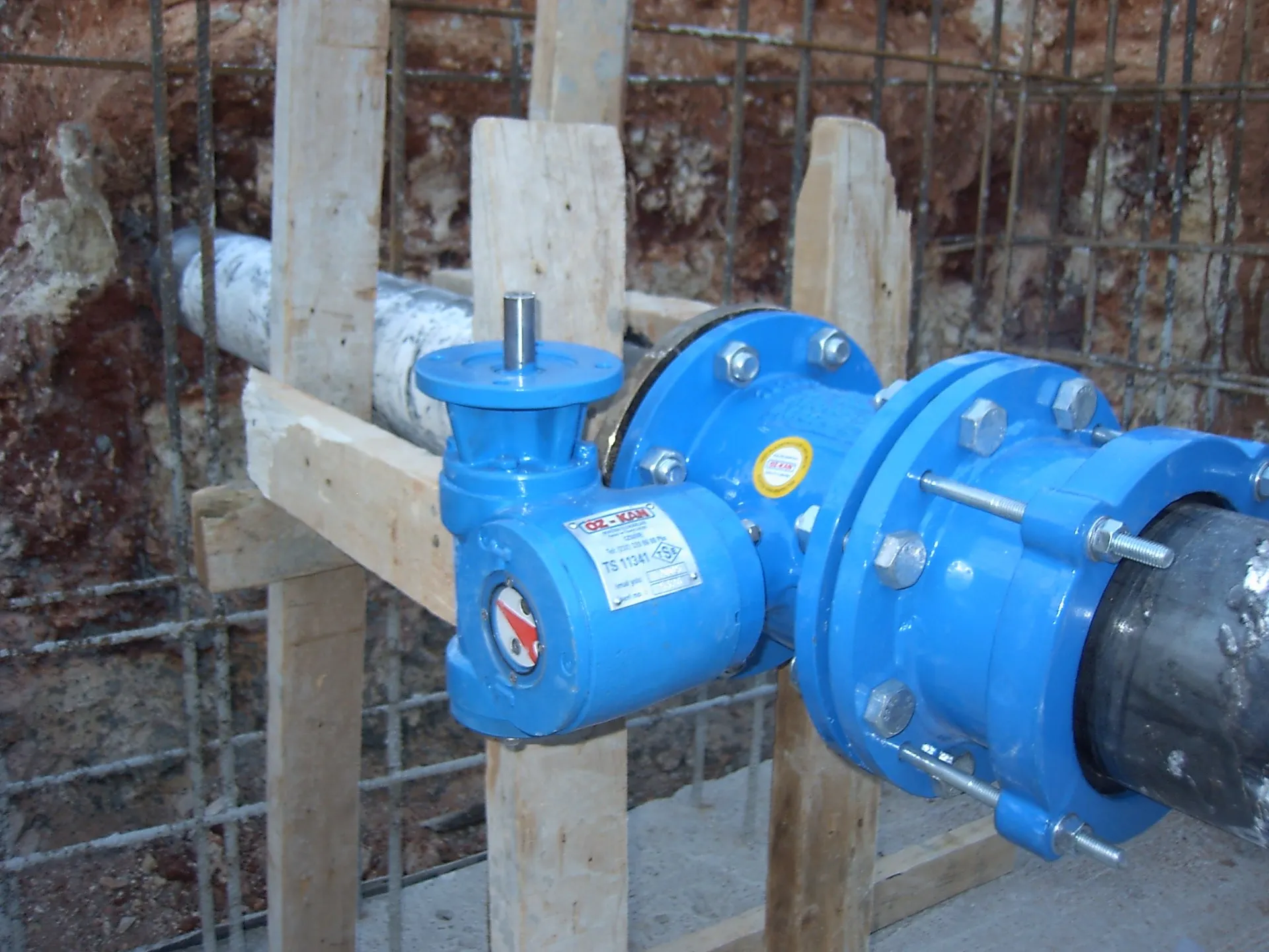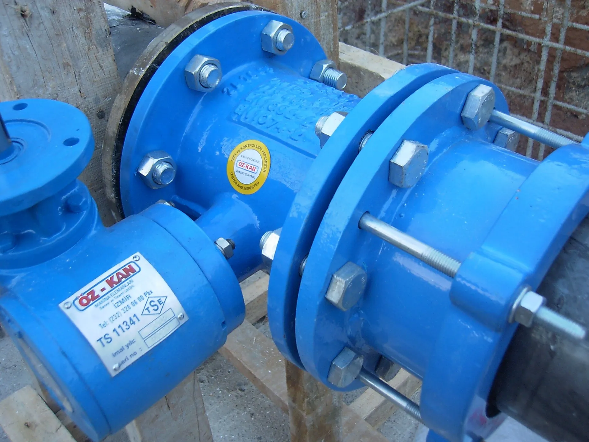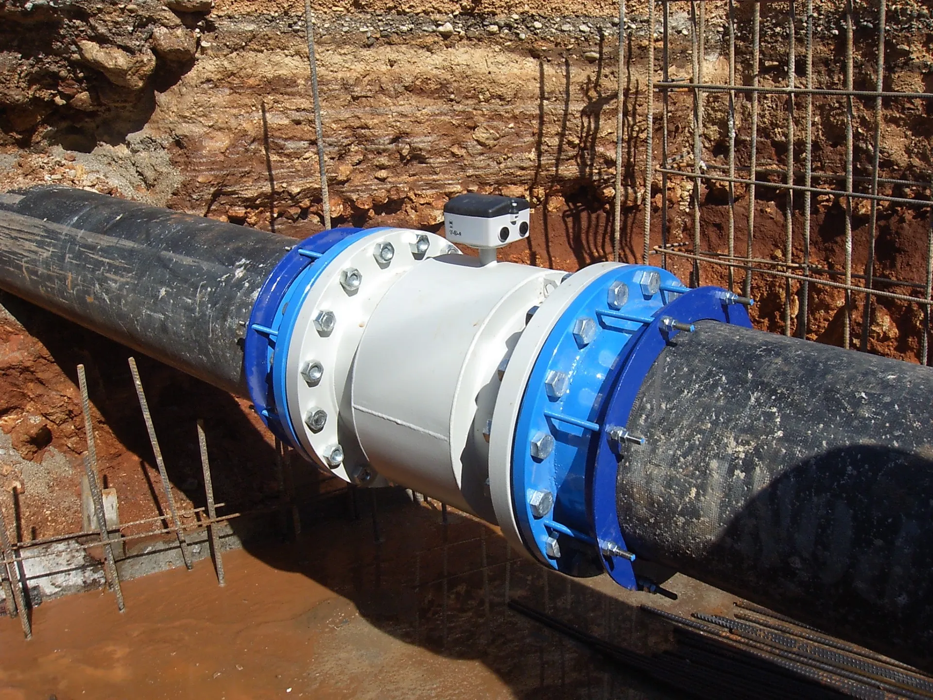
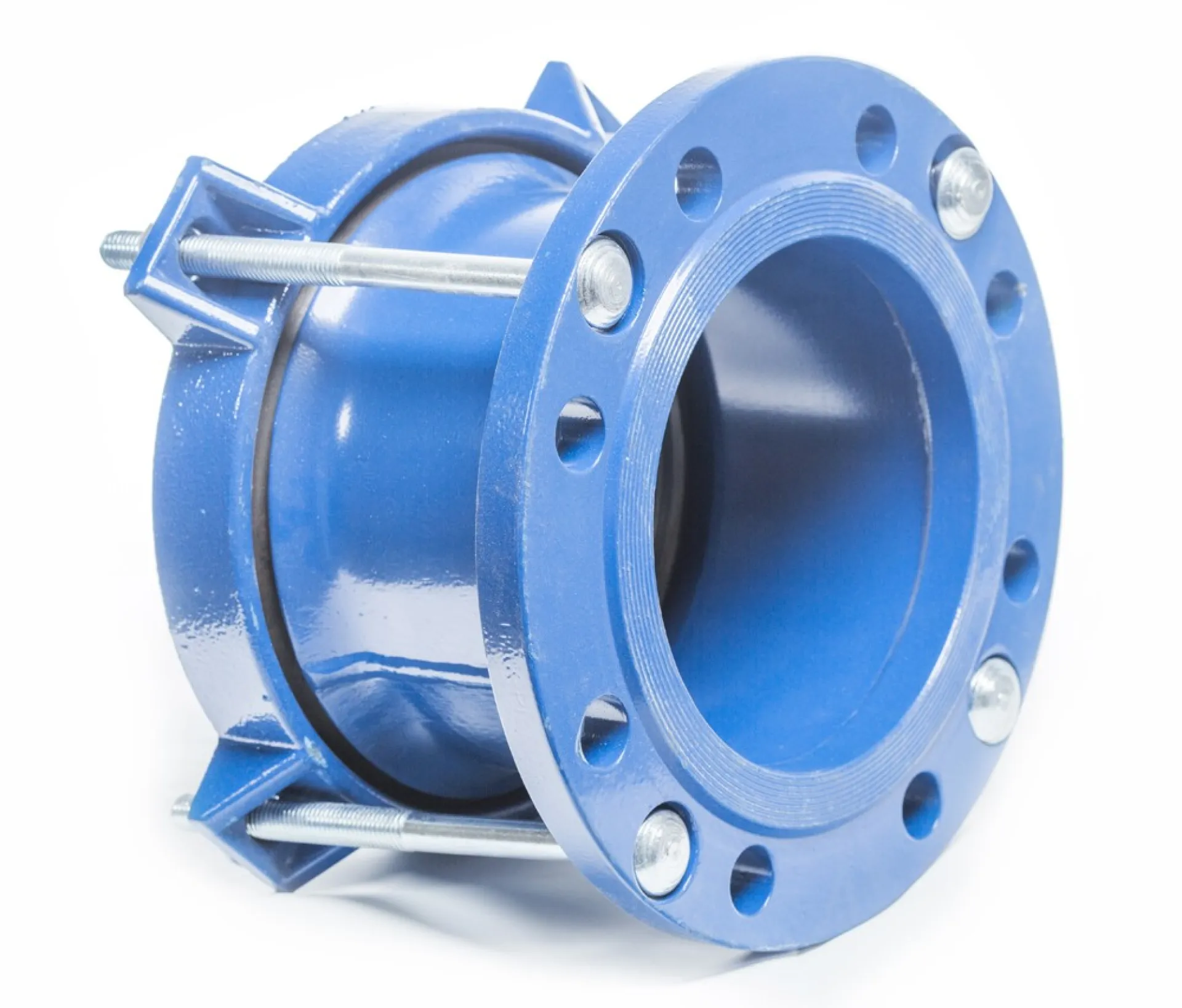
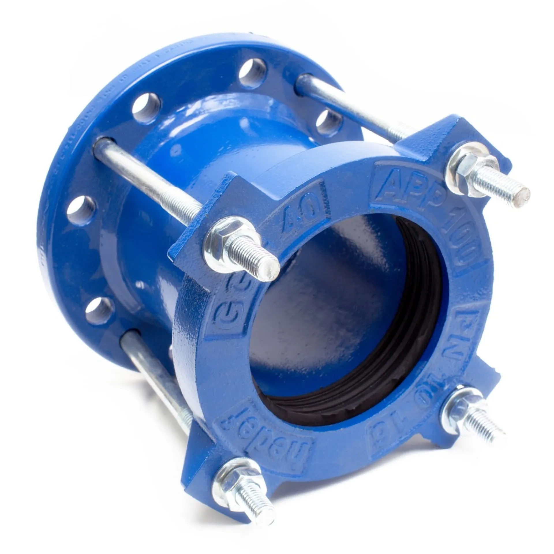
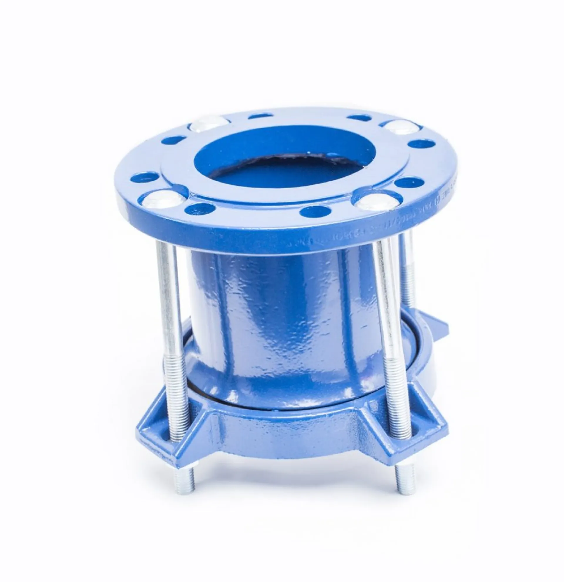
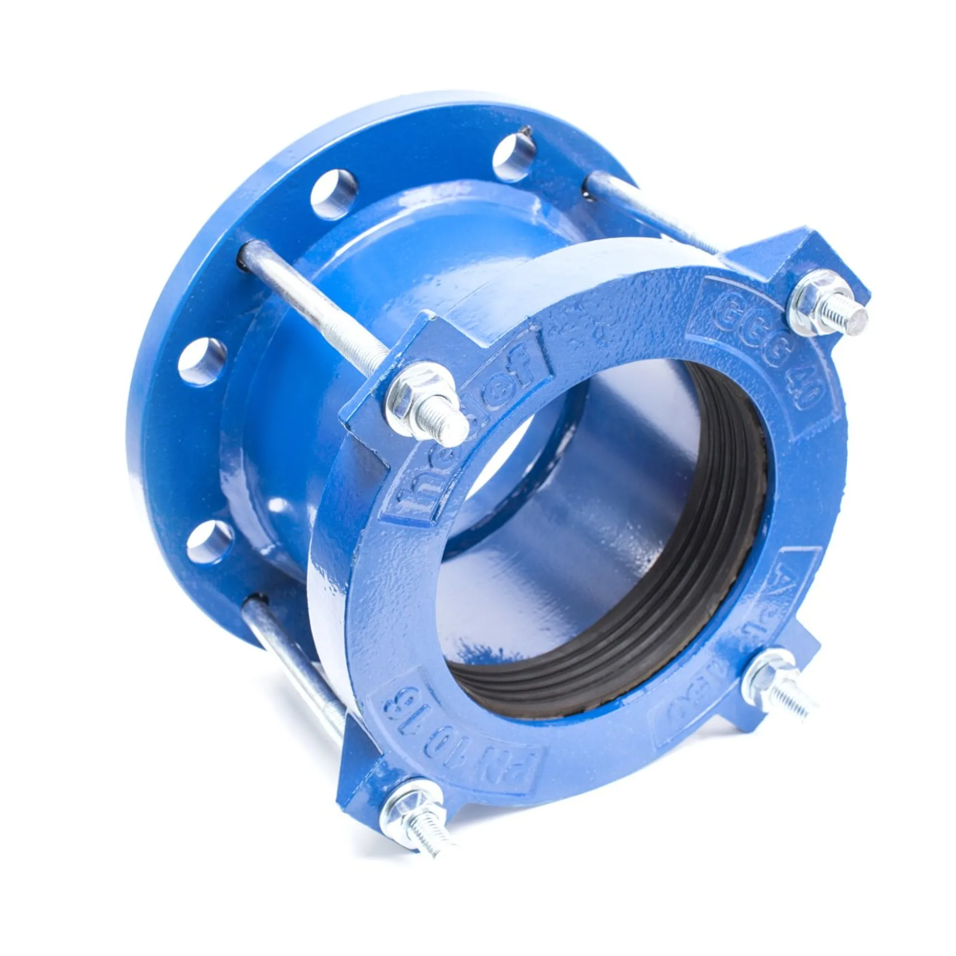
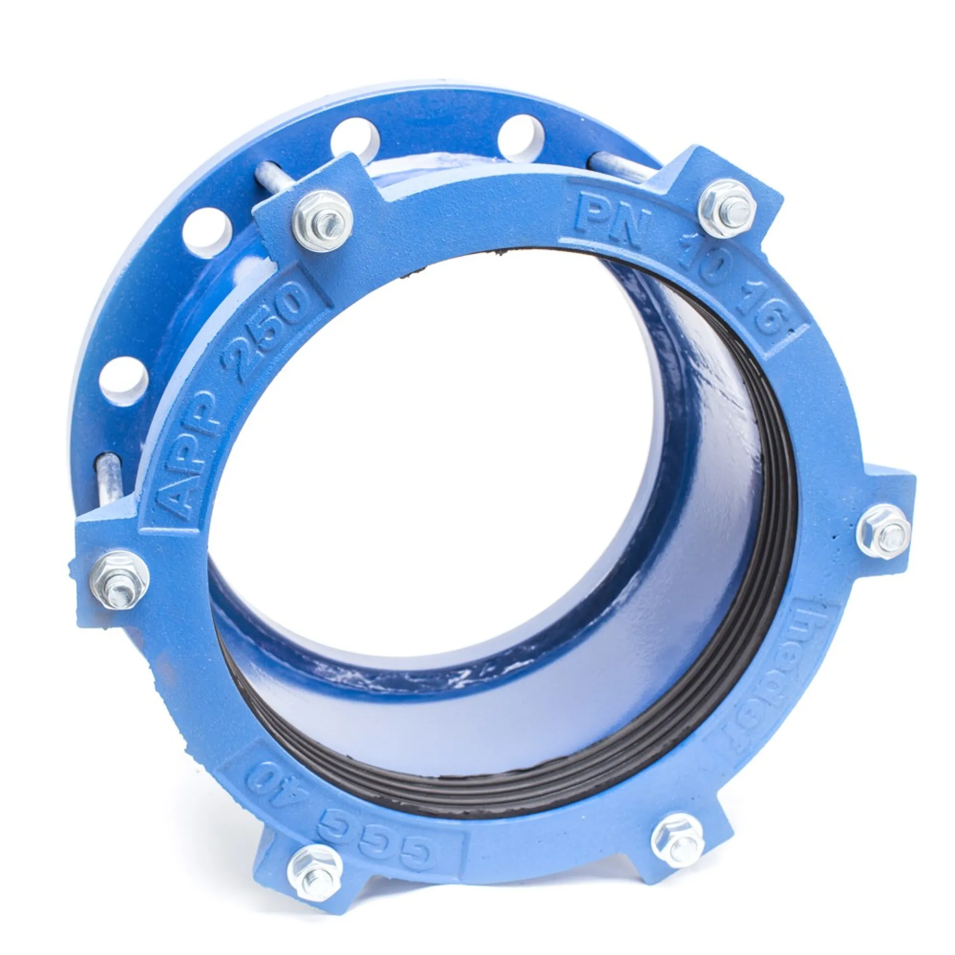
Universal Adaptation: Provides standard flanged connection and valve installation compatibility for all existing pipe types.
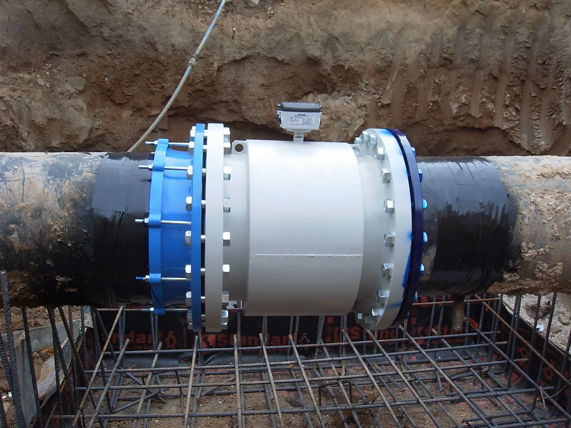
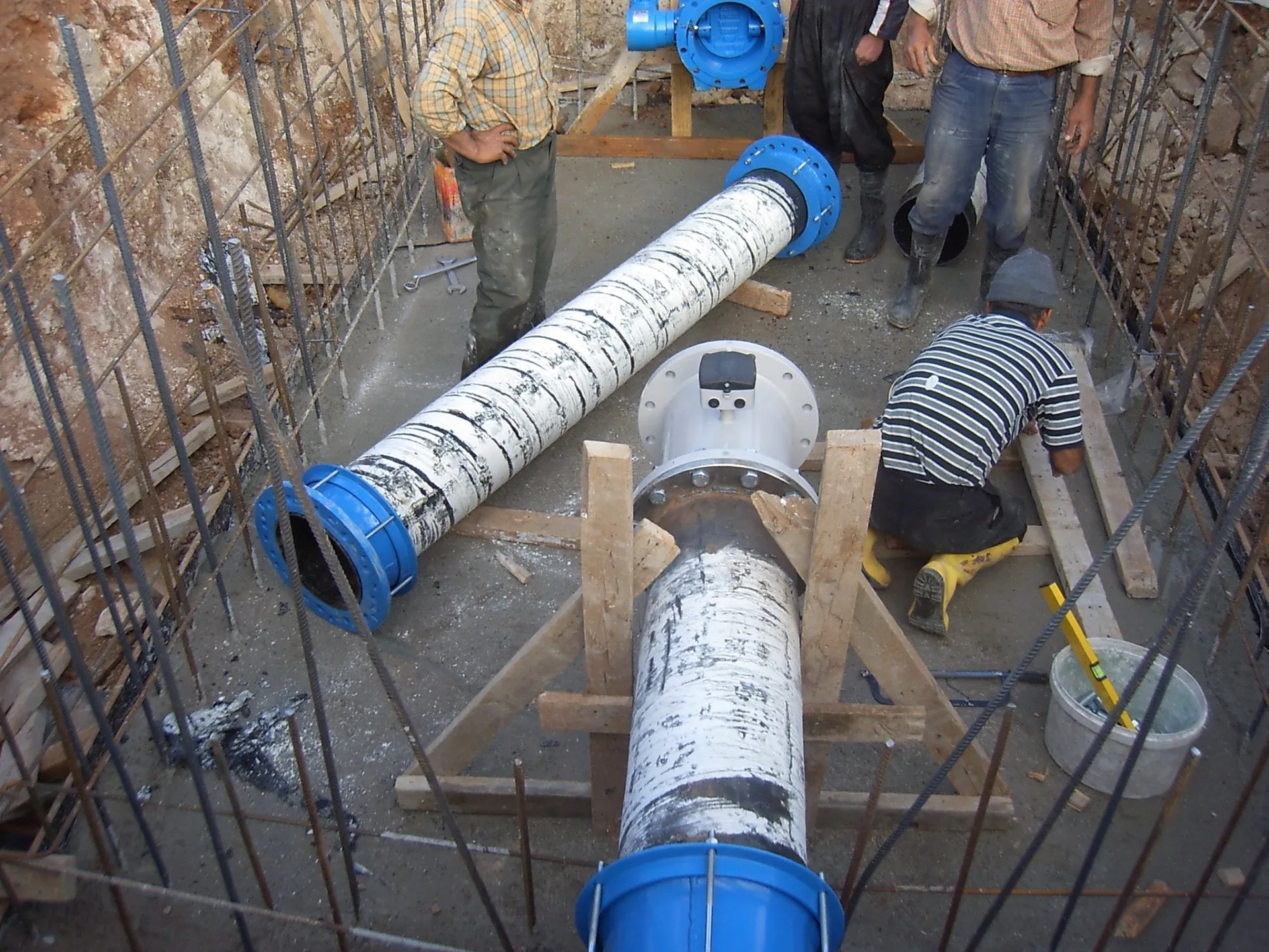
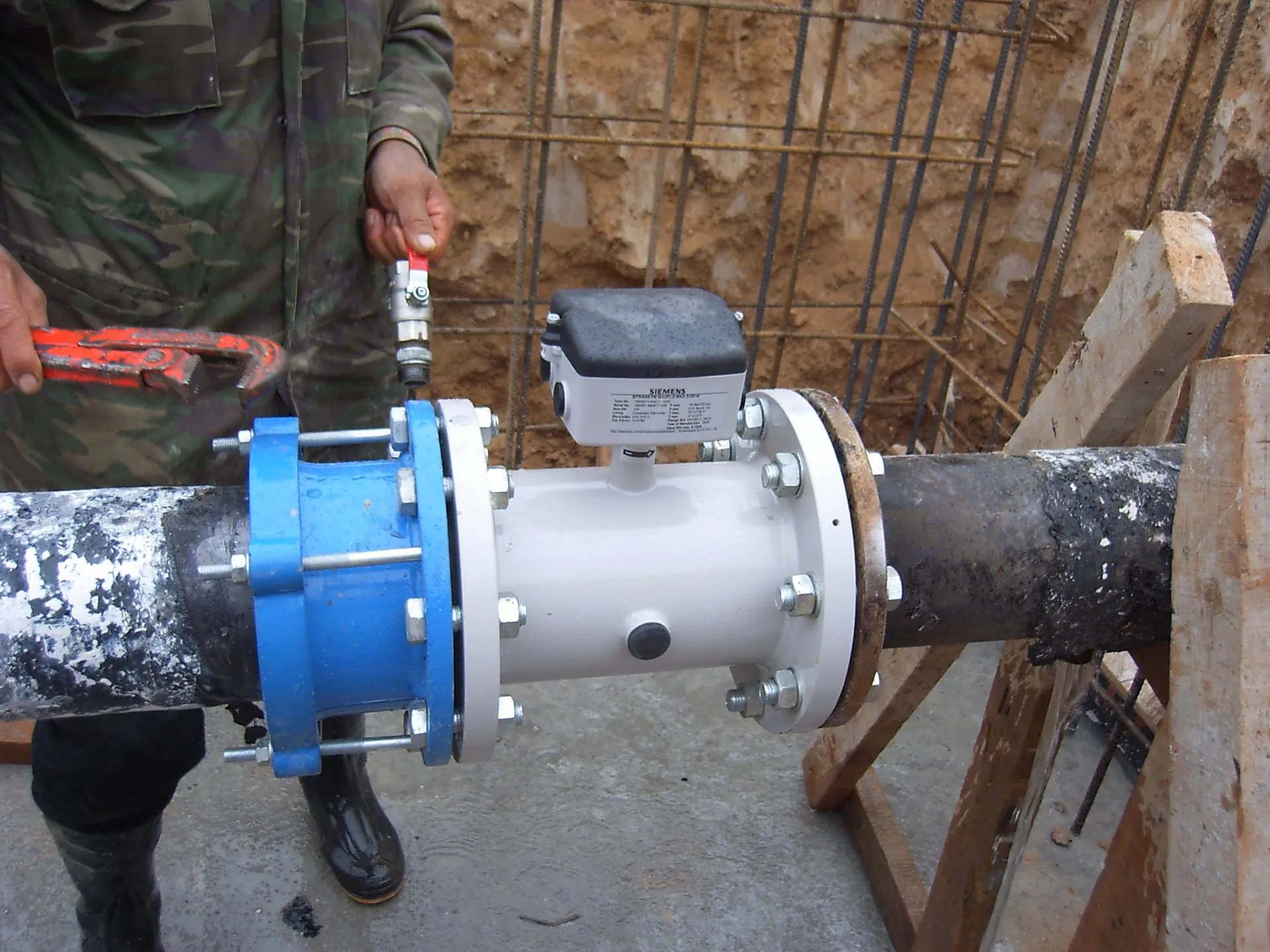
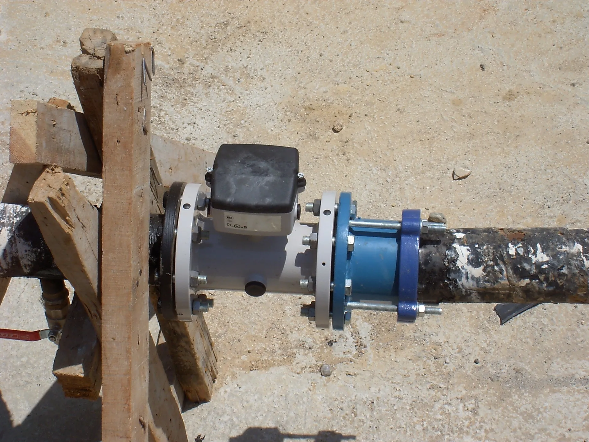
Economical Dismantling Solution: Practical and cost-effective design that can be used as a lightweight dismantling joint for valves, flow meters, and similar accessories.
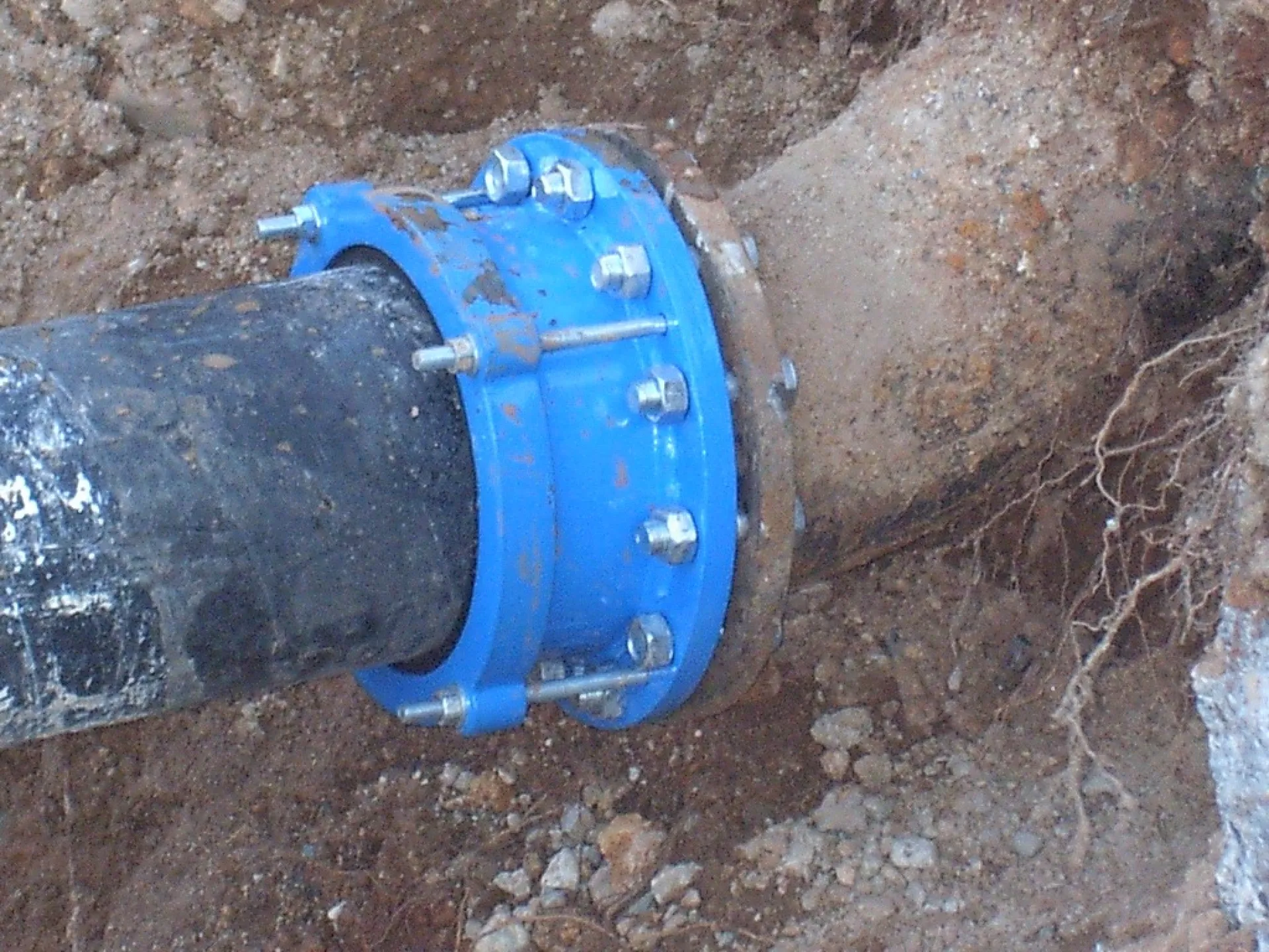
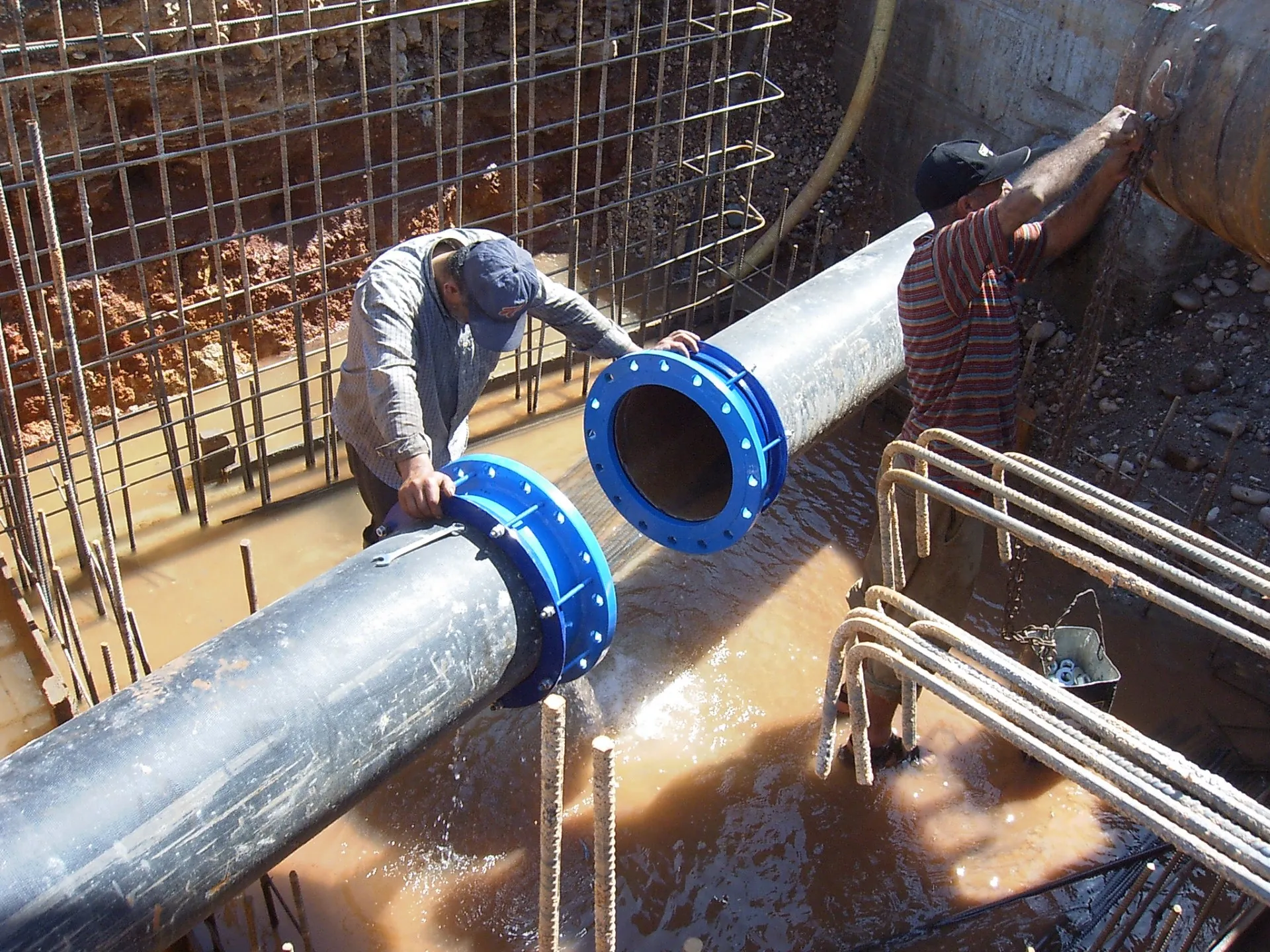
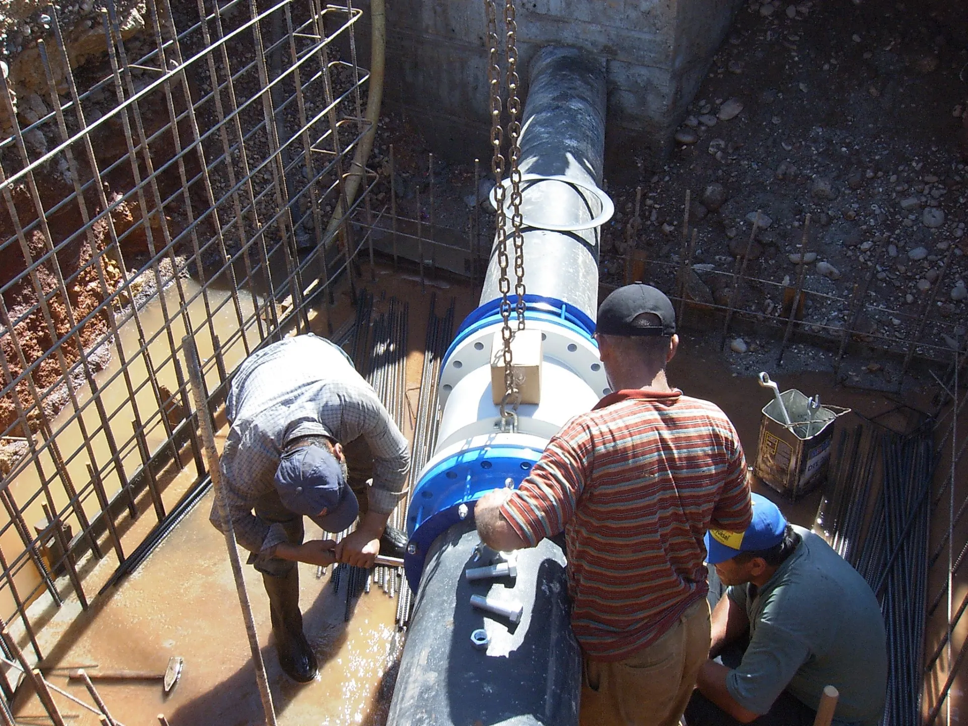
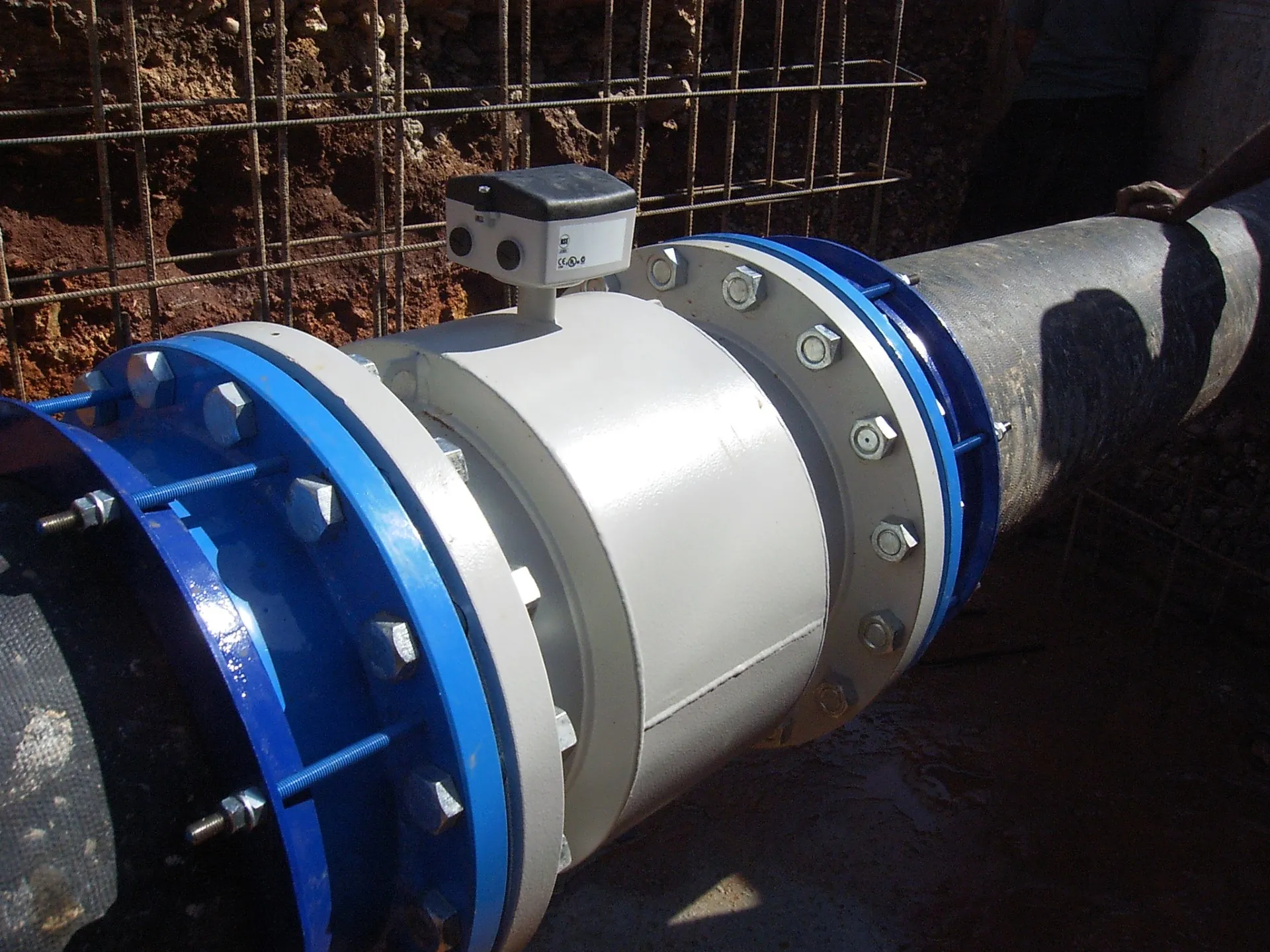
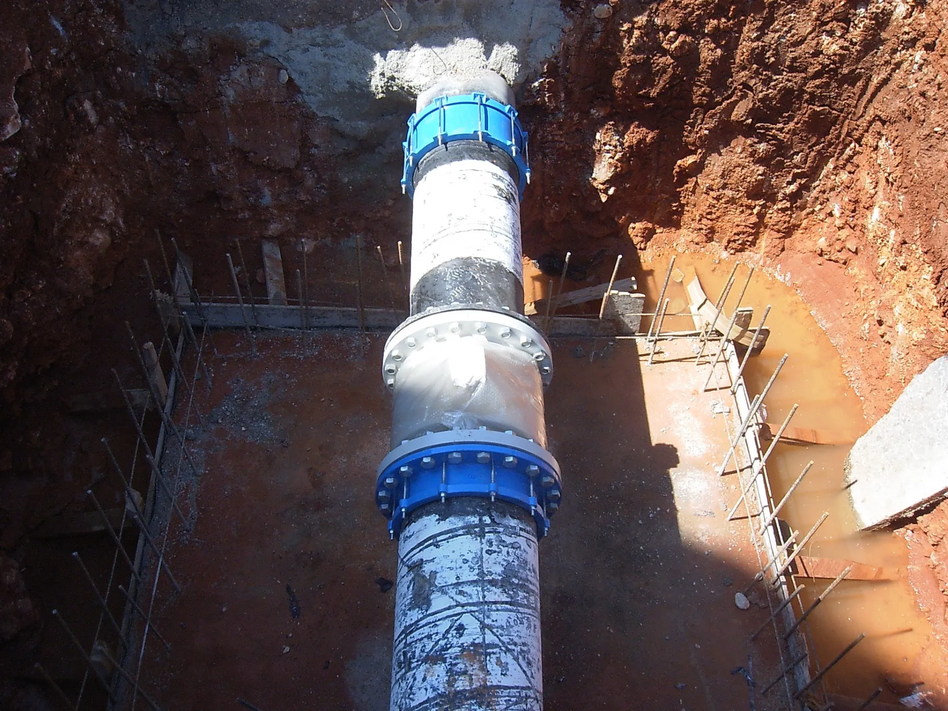
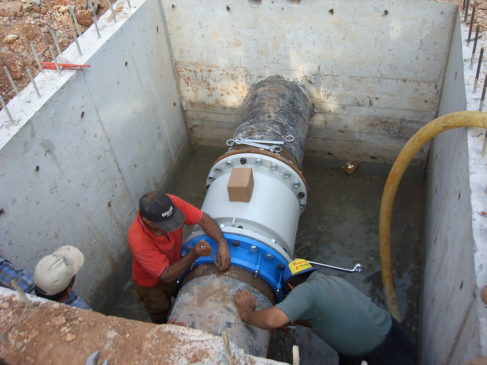
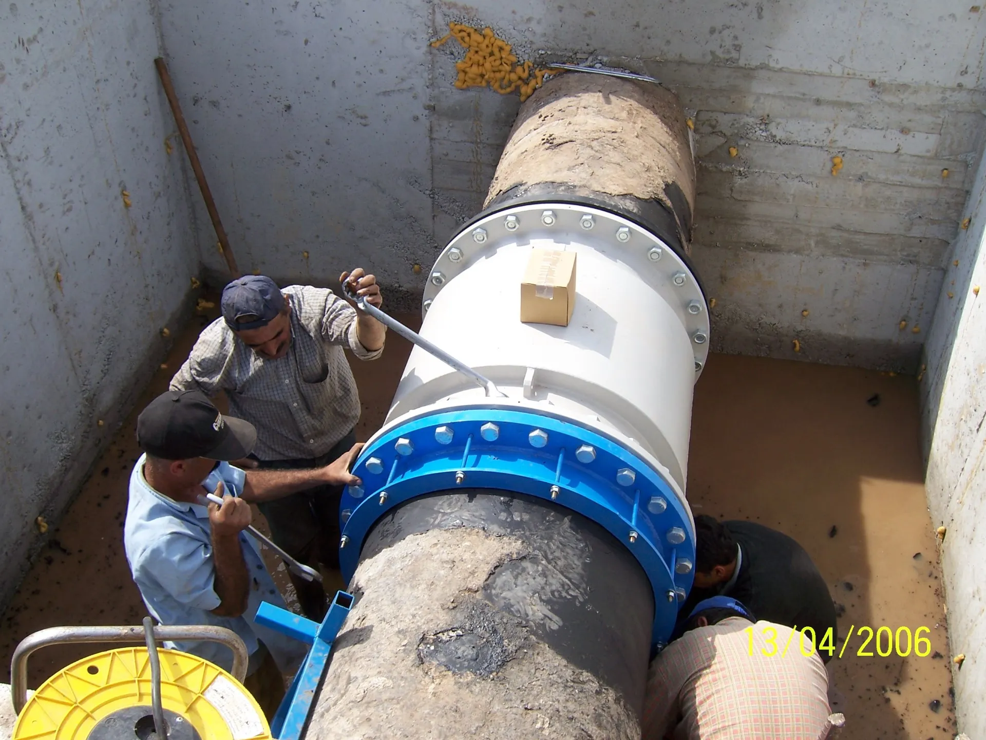
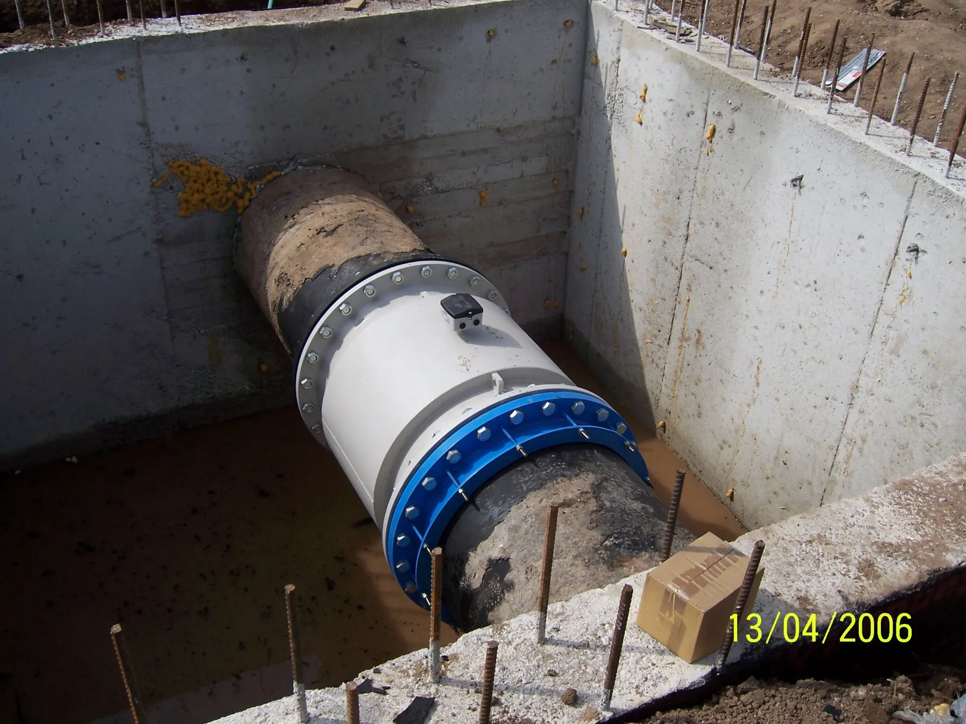
Weld-Free Installation: Ideal for valve and flow meter installation on pipelines where flow cannot be interrupted, thanks to its mechanical, non-welded design.
Full Compatibility: Converts pipes of different materials and diameters into standard flange systems.
KEY ADVANTAGES
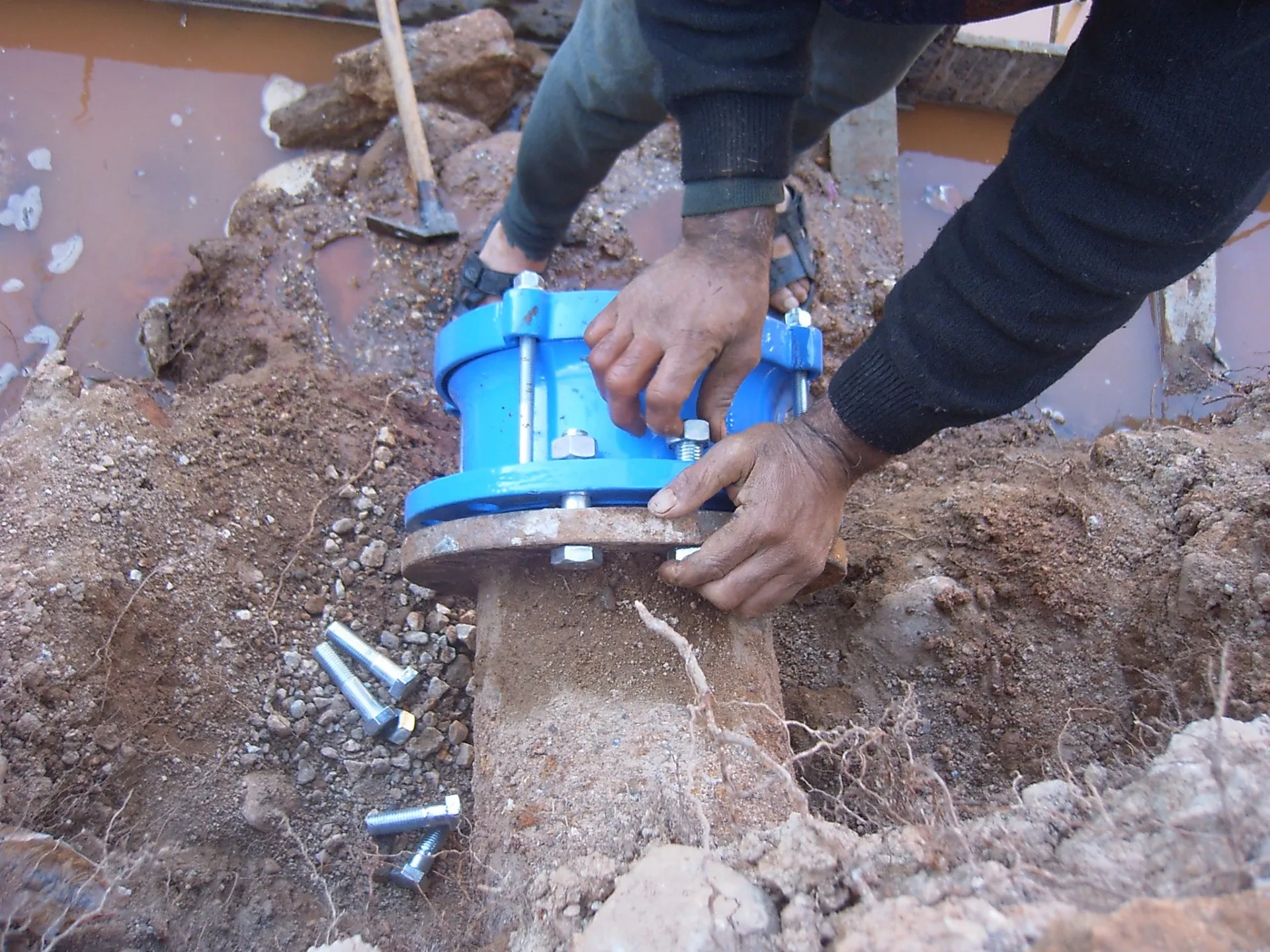
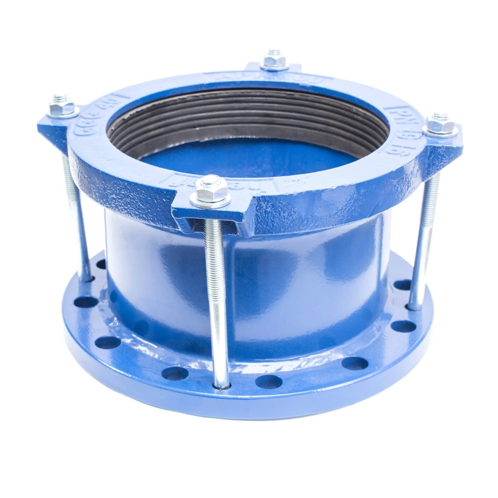
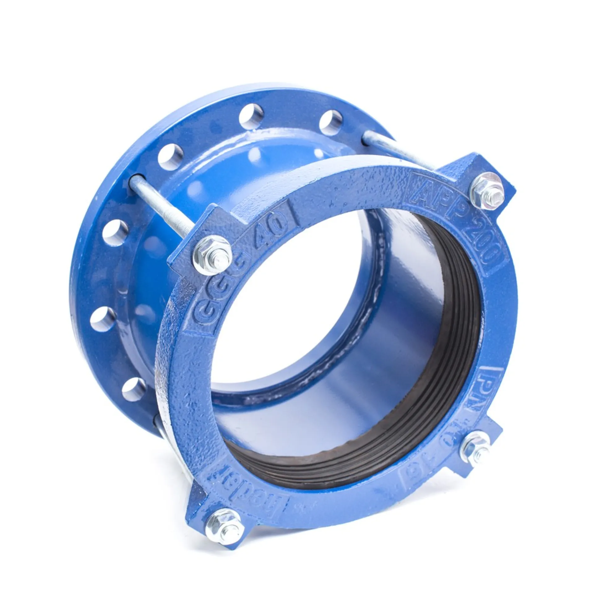
This instruction has been prepared for the safe and leak-tight installation of wide-tolerance flange adaptors used to connect different types of pipes (Ductile iron, Cast iron, Steel, PVC, PE, GRP, AC, etc.) to flanged equipment.
SAFETY NOTES
|
No |
Component Name |
Material and Technical Details |
|---|---|---|
|
1 |
Sleeve |
ST 37 Steel. High-strength structural body. |
|
2 |
End Rings |
Ductile Iron (GGG40/50) / ST 37 Steel. Pressure end caps applying force to the gasket. |
|
3 |
Flange |
Zinc-Coated ST 37 Çelik. Compatible with various flange standards |
|
4 |
Tee Bolts/Bolts |
Zinc-Coated Grade 8.8 Steel / AISI 304 / 316 Stainless Steel. High corrosion resistance. |
|
5 |
Conical Gasket |
EPDM / NBR. Pressure-responsive sealing technology. |
|
6 |
Nuts and Washers |
Zinc-Coated Grade 8.8 Steel / AISI 304 / 316 Stainless Steel. Secure locking system. |
|
7 |
Coating |
Epoxy / Thermoplastic. Long-lasting protection and durability. |
| REFERENCE DIAMETER (mm) | APP CODE | COMPATIBLE PIPE TYPES (mm) | Flange Side (mm) |
|---|---|---|---|
| 50 | APP-F 50 | 50 Steel, 63 HDPE, 63 PVC | 50 |
| 80 | APP-F 80 | 80 AC (PN 10), 80 Steel, 90 PVC, 90 HDPE, 80 Ductile, 80 CI | 80 |
| APP-F 80/2 | 110 PVC, 110 HDPE, 80 AC (PN 10) | 80, 100 | |
| 100 | APP-F 100 | 110 PVC, 110 HDPE, 100 AC (PN 10), 100 CI, 100 Steel, 100 Ductile | 100 |
| 125 | APP-F 125 | 125 AC (PN 10), 140 PVC, 140 HDPE, 125 Steel, 125 CI, 125 Ductile | 125 |
| 150 | APP-F 150/1 | 160 PVC, 160 HDPE, 150 Steel | 150 |
| APP-F 150/2 | 160 PVC, 160 HDPE, 180 PVC, 180 HDPE, 150 Steel, 150 CI, 150 Ductile, 150 AC (PN 10), | ||
| APP-F 150/3 | 150 AC (PN 12,5), PN12,5, 200 HDPE, 200 PVC | ||
| 200 | APP-F 200/1 | 225 PVC, 225 HDPE, 200 Steel, 200 Ductile | 200 |
| APP-F 200/2 | 200 AC (PN10), 225 PVC, 225 HDPE, 200 Ductile, 200 CI | ||
| APP-F 200/3 | 200 AC, (PN 12,5) PN 12,5, 250 PVC, 250 HDPE | ||
| 250 | APP-F 250/1 | 250 Ductile, 250 Steel, 250 CI | 250 |
| APP-F 250/2 | 250 AC (PN 10), 280 PVC, 280 HDPE | ||
| APP-F 250/3 | 250 AC (PN 12,5) | ||
| 300 | APP-F 300/1 | 315 PVC, 315 HDPE, 300 CI, 300 Steel, 300 Ductile | 300, 350 |
| APP-F 300/2 | 300 Ductile, 300 AC (PN 5) | ||
| APP-F 300/3 | 300 AC (PN 10), 355 PVC, 355 HDPE, 350 Steel | ||
| 350 | APP-F 350/1 | 300 AC (PN12,5), 350 Ductile, 350 CI, AC (PN 15) | 300, 350, 400 |
| APP-F 350/2 | 350 AC (PN 10), 400 PVC, 400 HDPE, 400 Steel | ||
| 400 | APP-F 400/1 | 400 Ductile, 400 CI, 400 GRP | 400, 450 |
| APP-F 400/2 | 400 AC (PN 10), 450 PVC, 450 HDPE, 450 Steel | ||
| 500 | APP-F 500/1 | 500 Steel, 500 HDPE, 500 PVC, 450 AC (PN 10) | 500 |
| APP-F 500/2 | 500 Ductile, 500 CI, 500 GRP | ||
| APP-F 500/3 | 500 AC (PN 10), 560 PVC, 560 HDPE | ||
| 600 | APP-F 600/1 | 600 Steel, 500 AC (PN15) | 600 |
| APP-F 600/2 | 600 Ductile, 600 CI, 630 PVC, 630 HDPE, 600 GRP | ||
| APP-F 600/3 | 600 AC (PN 10), 600 AC (PN12,5) | ||
| 700 | APP-F 700 | AC, Steel, Ductile, GRP, PE, CI | 700 |
| 800 | APP-F 800 | AC, Steel, Ductile, GRP, PE, CI | 800 |
| 900 | APP-F 900 | AC, Steel, Ductile, GRP, PE, CI | 900 |
| 1000 | APP-F 1000 | AC, Steel, Ductile, GRP, PE, CI | 1000 |
| 1200 | APP-F 1200 | Steel, Ductile, GRP, PE | 1200 |
| 1400 | APP-F 1400 | Steel, Ductile, GRP, PE | 1400 |
| 1600 | APP-F 1600 | Steel, Ductile, GRP, PE | 1600 |
| 1600-3400 | APP-F 1600--3400 | Steel, Ductile, GRP | |
| Please specify the pressure classes of the flanges when ordering. | |||
| Custom production is available for pipe diameters not listed. | |||