APP-F/GGG

Ductile Iron Flange Adaptor

Secure and Durable Connection for Flanged Systems: APP Technology

APP Ductile Iron Flange Adaptors are developed to provide secure and leak-tight connections between pipelines and flanged equipment such as valves, pumps, and other systems. Thanks to their high-strength ductile iron (GGG40/50) structure, they deliver reliable and long-lasting performance even under heavy-duty operating conditions.

High-Strength Structure: GGG40/50 ductile iron body and pressure ring ensure high resistance against impact and high pressure.
Angular Deflection Tolerance: Provides installation flexibility by compensating for ground settlement and pipeline misalignment.
Easy Installation: Mechanical connection design enables fast installation without welding, even in pipelines where flow cannot be interrupted.
Universal Flange Dimensions: Standard-compliant flange design ensures full compatibility with all flange norms.

KEY ADVANTAGES

  • Compatible with various pipe materials (Ductile iron, Cast iron, AC, PVC, PE, GRP, etc.)
  • Easily integrates different pipe types into flanged systems
  • Facilitates dismantling and maintenance of flanged valves and equipment
  • Compact design suitable for confined spaces and valve chambers
  • Absorbs angular deviations up to 3° and ground movements
  • Expansion and contraction tolerance up to 5 mm
  • Fast installation under harsh site conditions, reducing labor costs
  • High resistance to impact and mechanical loads
  • Pıtable water and infrastructure pipelines
  • Industrial pipeline systems
  • Treatment plants and pumping stations
  • Valve and equipment connections
  • Flow meter and instrumentation installations
  • Transition points between different pipe diameters

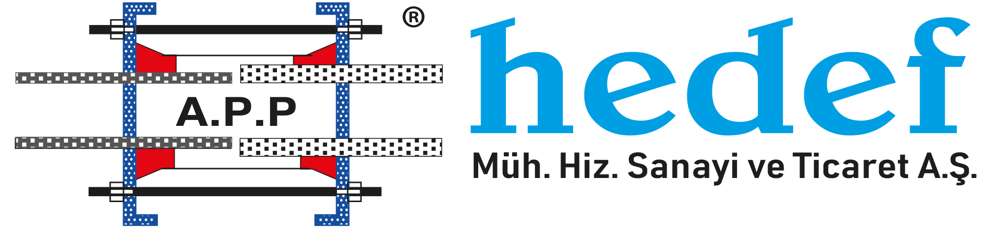
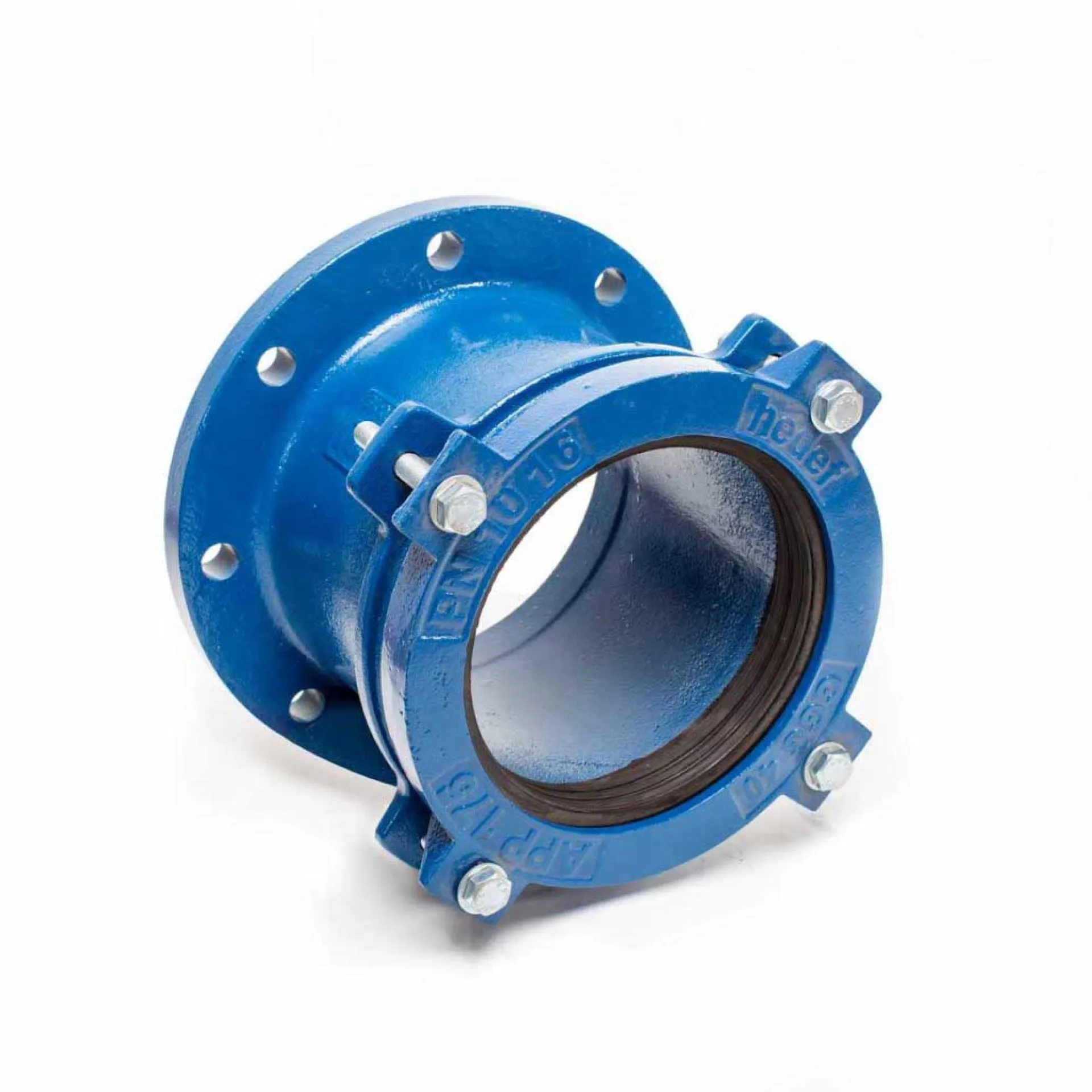
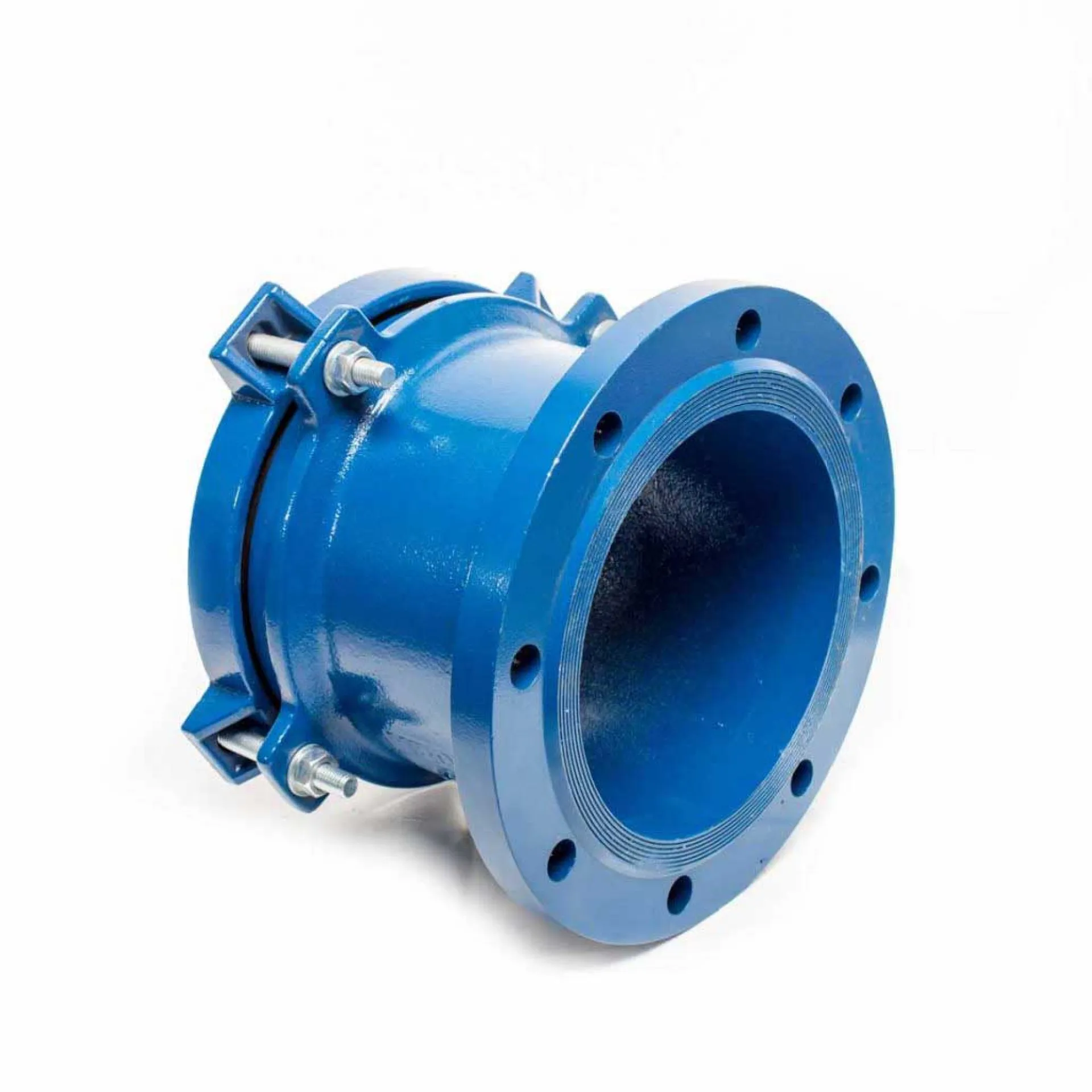
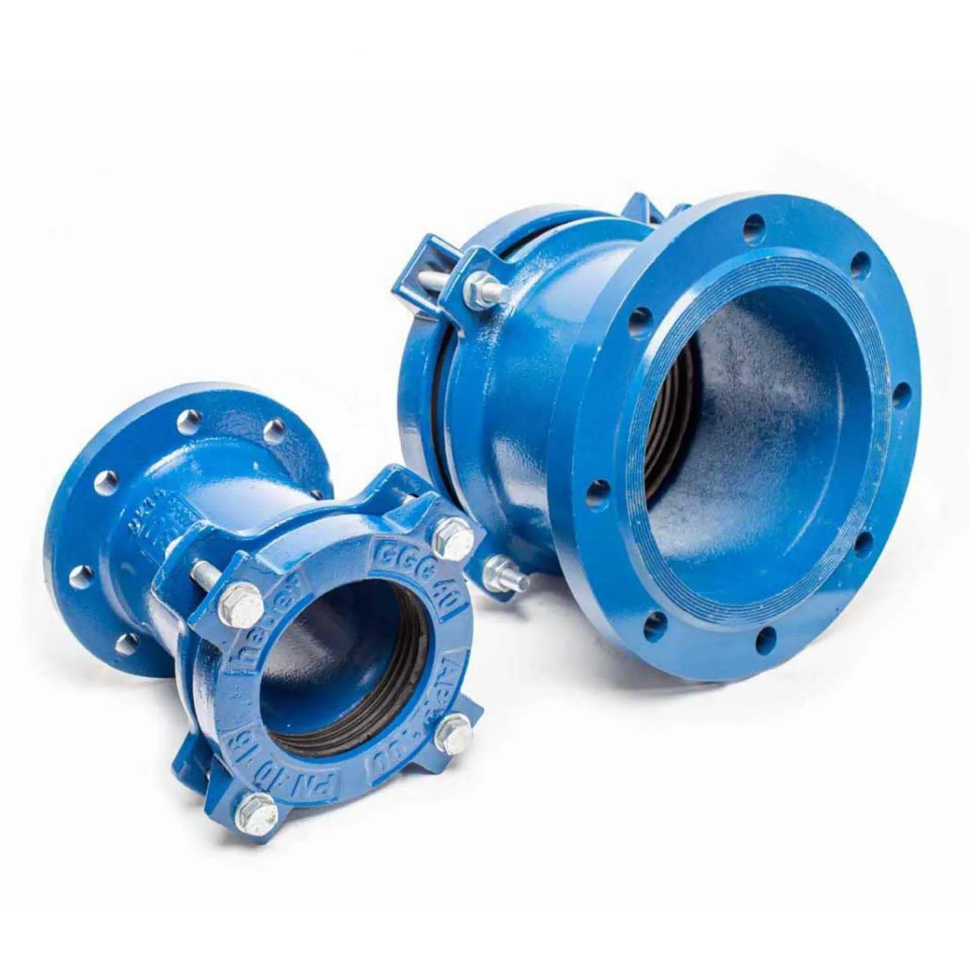
This instruction has been prepared for the safe and leak-tight installation of wide-tolerance ductile iron flange adaptors used to connect different types of pipes (Ductile iron, Cast iron, Steel, PVC, PE, GRP, AC, etc.) to flanged equipment.

  1. Pre-Installation Preparation
  • Product Check:
    Verify the label information on the adaptor (DN size and tolerance range) and ensure it is suitable for the outer diameters of the pipes to be connected.
  • Flange Compatibility:
    Check that the adaptor flange matches the mating flange (PN10, PN16, PN25, etc.) in terms of bolt hole number and pitch circle diameter (PCD).
  • Pipe Cutting:
    Cut the pipes perpendicular (approx. 90°) to the pipe axis. Uneven cuts may prevent proper seating of the sealing gasket.
  • Surface Cleaning:
    Clean rust, dirt, scale, and old coatings from the pipe ends using a wire brush.
    The surface in contact with the sealing gasket must be smooth and clean.
  • Chamfering (If Required):
    Apply an external chamfer of approximately 30° to the pipe end if necessary.
    This prevents damage to the gasket during insertion.
  1. Positioning and Marking
  • Insertion Depth Marking:
    Measure the adaptor body length and mark a reference line on the pipe equal to half of the adaptor length.
  • Pipe Alignment:
    Flange adaptors typically allow up to ±3° angular deviation; however, proper alignment is recommended for optimal performance.
  1. Installation Steps
  • Lubrication:
    Apply a silicone-based lubricant suitable for potable water to the gasket and pipe end.
    (Do not use oil-based lubricants as they may damage the gasket.)
  • Placement:
    Slide the adaptor loosely onto the pipe.
  • Flange Connection:
    Align the adaptor flange with the mating flange (valve or equipment).
    Insert a standard flange gasket between the flanges.
  1. Tightening Procedure (Critical Step)
  • Flange Bolt Tightening:
    First, tighten the flange bolts in a star (crosswise) pattern to fix the adaptor in position.
  • Adaptor Bolt Tightening:
    Tighten the adaptor bolts diagonally (e.g., 12–6 o’clock, 3–9 o’clock).
    This ensures even load distribution on the gasket.
  • Gradual Tightening:
    First hand-tighten all bolts, then tighten gradually in multiple passes using a wrench.
  1. Final Check and Testing
  • Visual Inspection:
    Ensure that the gap between the pressure flanges and the adaptor body is uniform around the entire circumference.
  • Pressure Test:
    Perform a low-pressure leak test before commissioning the pipeline.
    If leakage is detected, recheck and retighten the bolts.

SAFETY NOTES

  • Wear protective gloves and safety footwear during installation.
  • For large-diameter adaptors, use pipe supports or blocking elements to prevent excessive load on the adaptor.
  • Ensure that the protective coating of bolts (galvanized, Dacromet, etc.) is not damaged to maintain corrosion resistance.

No

Component Name

Material and Technical Details

1

Sleeve

Ductile Iron (GGG40/50). High-strength structural body.

2

End Rings

Ductile Iron (GGG40/50). Pressure end caps applying force to the gasket.

3

Flange

Ductile Iron (GGG40/50). Compatible with various flange standards

4

Tee Bolts/Bolts

Zinc-Coated Grade 8.8 Steel / AISI 304 / 316 Stainless Steel. High corrosion resistance.

5

Conical Gasket

EPDM / NBR. Pressure-responsive sealing technology.

6

Nuts and Washers

Zinc-Coated Grade 8.8 Steel / AISI 304 / 316 Stainless Steel. Secure locking system.

7

Coating

Epoxy / Thermoplastic. Long-lasting protection and durability.

REFERENCE DIAMETER (mm) APP CODE COMPATIBLE PIPE TYPES (mm) FLANGE SIDE (mm)
100 APP-F/GGG 100 110 PVC, 110 HDPE, 100 AC (PN 10), 100 CI, 100 Steel, 100 Ductile 100
125 APP-F/GGG 125 125 AC (PN 10), 140 PVC, 140 HDPE, 125 Steel, 125 CI, 125 Ductile 125
150 APP-F/GGG 150/1 160 PVC, 160 HDPE, 150 Steel 150
APP-F/GGG 150/2 160 PVC, 160 HDPE, 180 PVC, 180 HDPE, 150 Steel, 150 CI, 150 Ductile, 150 AC (PN 10),
APP-F/GG 150/3 150 AC (PN 12,5), 200 HDPE, 200 PVC
175 APP-F/GGG 175 175 AC (PN 10), 200 Steel 200
200 APP-F/GGG 200/1 225 PVC, 225 HDPE, 200 Steel, 200 Ductile 200
APP-F/GGG 200/2 200 AC (PN10), 225 PVC, 225 HDPE, 200 Ductile, 200 CI
250 APP-F/GGG 250/1 250 Ductile, 250 Steel, 250 CI 250
APP-F/GGG 250/2 250 AC (PN 10), 280 PVC, 280 HDPE
300 APP-F/GGG 300/1 315 PVC, 315 HDPE, 300 CI, 300 Steel, 300 Ductile 300
APP-F/GGG 300/2 300 Ductile, 300 AC (PN 5)
APP-F/GGG 300/3 300 AC (PN 10), 355 PVC, 355 HDPE, 350 Steel
350 APP-F/GGG 350 300 AC (PN12,5), 350 Ductile, 350 CI, AC (PN 15) 350
Please specify the pressure classes of the flanges when ordering.
Custom production is available for pipe diameters not listed.
up