- Potable water transmission and infrastructure lines
- Industrial pipeline systems
- Treatment plants and pumping stations
- New pipeline connections and system integration
- Maintenance, repair, and rehabilitation works
- Integration of different pipeline systems
- Fire hydrant and high-pressure pipeline systems
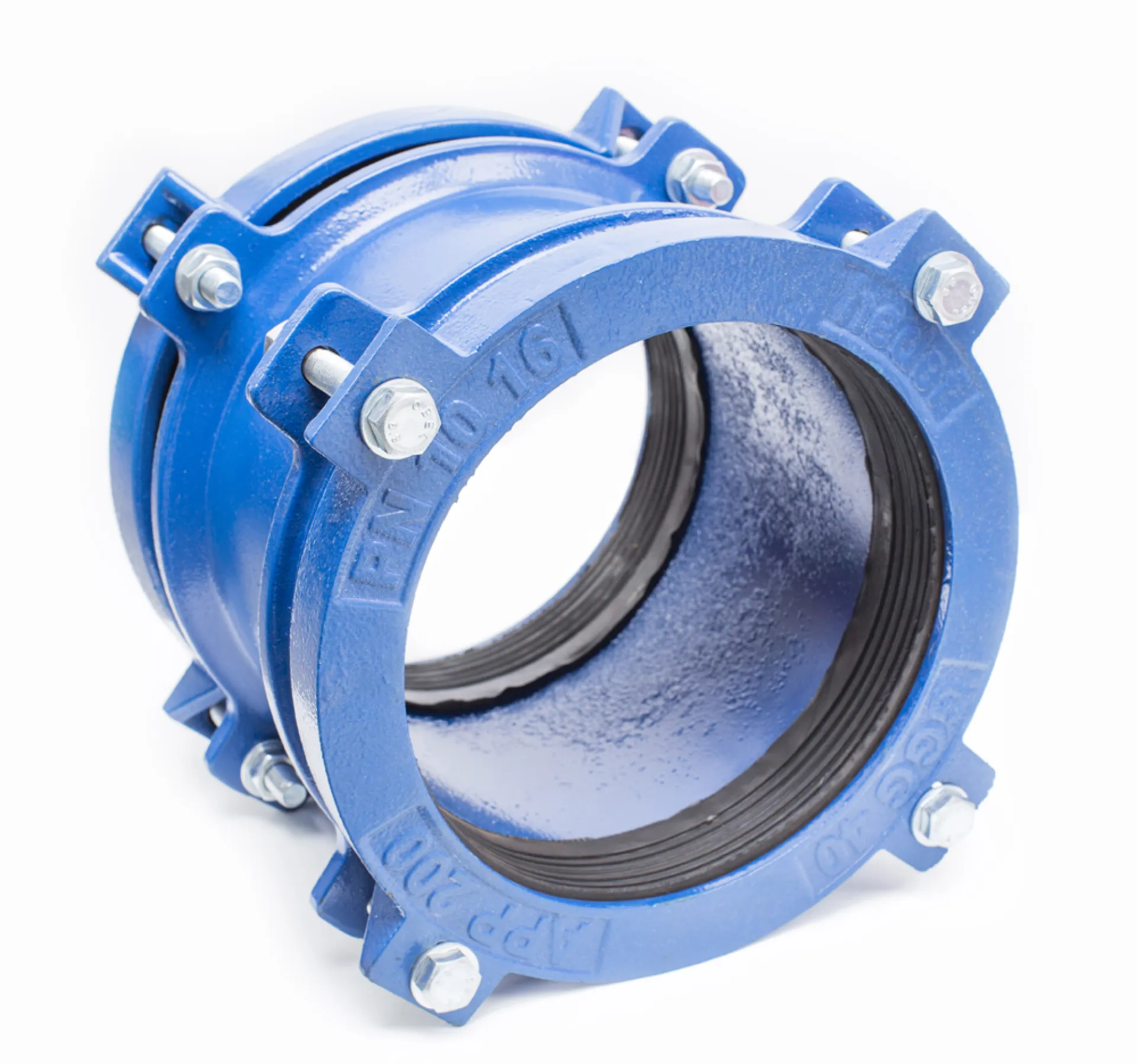
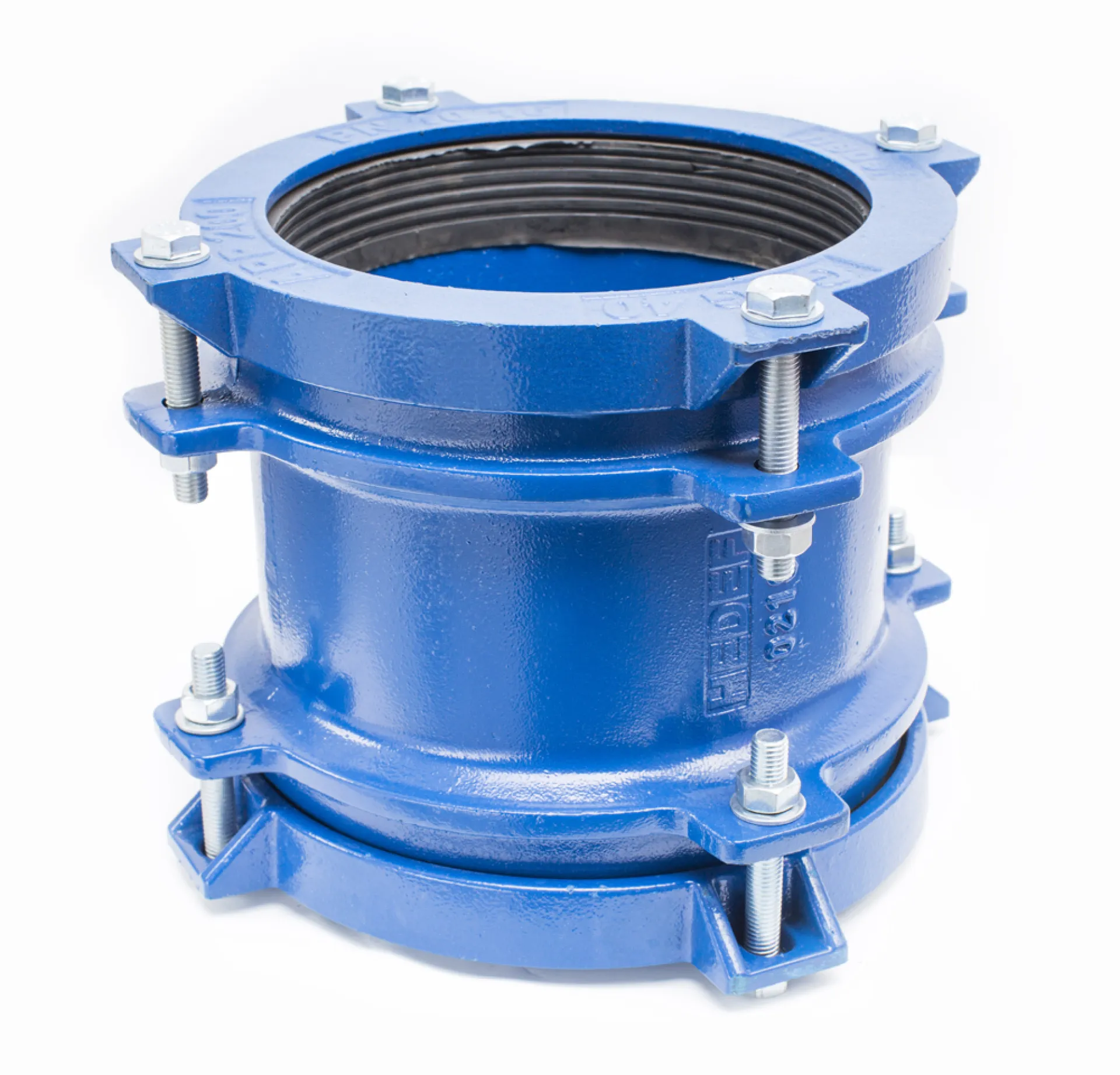
This instruction has been prepared for the safe and leak-tight installation of wide-tolerance ductile iron couplings used to connect different types of pipes (Ductile iron, Cast iron, Steel, PVC, PE, GRP, AC, etc.).
- Pre-Installation Preparation
- Product Check:
Verify the label information on the adaptor (DN size and tolerance range) and ensure it is suitable for the outer diameters of the pipes to be connected.
- Pipe Cutting:
Cut the pipes perpendicular (approx. 90°) to the pipe axis. Uneven cuts may prevent proper seating of the sealing gasket.
- Surface Cleaning:
Clean rust, dirt, scale, and old coatings from the pipe ends using a wire brush.
The surface in contact with the sealing gasket must be smooth and clean.
- Chamfering (If Required):
Apply an external chamfer of approximately 30° to the pipe ends if necessary.
This prevents damage to the gasket during insertion.
- Positioning and Marking
- Insertion Depth Marking:
Measure the adaptor body length and mark a reference line on the pipe equal to half of the adaptor length.
- Pipe Alignment:
Ensure both pipes are aligned as closely as possible.
Universal adaptors can typically accommodate up to ±6° angular deviation; however, proper alignment is recommended for optimal performance.
- Installation Steps
- Lubrication:
Apply a silicone-based lubricant suitable for potable water to the gasket and pipe ends.
(Do not use oil-based lubricants as they may damage the gasket.)
- Placement:
Slide the adaptor loosely onto the first pipe.
Bring the second pipe into position and center the adaptor so that it equally covers both pipe ends (aligned with the reference marks).
- Gap Control:
Ensure a gap of at least 10–20 mm between the pipe ends to allow for thermal expansion and settlement.
- Tightening Procedure (Critical Step)
- Cross Tightening:
Tighten the bolts in a diagonal (crosswise) sequence (e.g., 12–6 o’clock, 3–9 o’clock).
This ensures even pressure distribution on the gasket.
- Gradual Tightening:
First hand-tighten all bolts, then tighten gradually in multiple passes using a wrench.
- Final Check and Testing
- Visual Inspection:
Check that the gap between the pressure flanges and the adaptor body is uniform around the entire circumference.
- Pressure Test:
Perform a low-pressure leak test before commissioning the pipeline.
If leakage is detected, recheck and retighten the bolts.
SAFETY NOTES
- Wear protective gloves and safety footwear during installation.
- For large-diameter adaptors, use pipe supports or blocking elements to prevent excessive load on the adaptor.
- Ensure that the protective coating of bolts (galvanized, Dacromet, etc.) is not damaged to maintain corrosion resistance.
|
No
|
Component Name
|
Material and Technical Details
|
|
1
|
Sleeve
|
Ductile Iron (GGG40/50). High-strength structural body.
|
|
2
|
End Rings
|
Ductile Iron (GGG40/50). Pressure end caps applying force to the gasket.
|
|
3
|
Tee Bolts/Bolts
|
Zinc-Coated Grade 8.8 Steel / AISI 304 / 316 Stainless Steel. High corrosion resistance.
|
|
4
|
Conical Gasket
|
EPDM / NBR. Pressure-responsive sealing technology.
|
|
5
|
Nuts and Washers
|
Zinc-Coated Grade 8.8 Steel / AISI 304 / 316 Stainless Steel. Secure locking system.
|
|
6
|
Coating
|
Epoxy / Thermoplastic. Long-lasting protection and durability.
|
| REFERENCE DIAMETER (mm) |
APP CODE |
COMPATIBLE PIPE TYPES (mm) |
| 100 |
APP-GGG 100 |
110 PVC, 110 HDPE, 100 AC (PN 10), 100 CI, 100 Steel, 100 Ductile |
| 150 |
APP-GGG 150/1 |
160 PVC, 160 HDPE, 150 Steel |
| APP-GGG 150/2 |
160 PVC, 160 HDPE, 180 PVC, 180 HDPE, 150 Steel, 150 CI, 150 Ductile, 150 AC (PN 10), |
| APP-GGG 150/3 |
150 AC (PN 12,5), PN12,5, 200 HDPE, 200 PVC |
| 175 |
APP-GGG 175 |
175 AC (PN 10), 200 Steel |
| 200 |
APP-GGG 200/1 |
225 PVC, 225 HDPE, 200 Steel, 200 Ductile |
| APP-GGG 200/2 |
200 AC (PN10), 225 PVC, 225 HDPE, 200 Ductile, 200 CI |
| 250 |
APP-GGG 250/1 |
250 Ductile, 250 Steel, 250 CI |
| APP-GGG 250/2 |
250 AC (PN 10), 280 PVC, 280 HDPE |
| 300 |
APP-GGG 300/1 |
315 PVC, 315 HDPE, 300 CI, 300 Steel, 300 Ductile |
| APP-GGG 300/2 |
300 Ductile, 300 AC (PN 5) |
| APP-GGG 300/3 |
300 AC (PN 10), 355 PVC, 355 HDPE, 350 Steel |
| 350 |
APP-GGG 350 |
300 AC (PN12,5), 350 Ductile, 350 CI, AC (PN 15) |
| Custom production is available for pipe diameters not listed. |