APP-DRS

APP Type Bend

Maximum Flexibility and Safe Direction Change in Pipelines: APP Elbow Technology

APP Type Elbows are high-performance engineering solutions designed to change the direction of pipelines, featuring wide-tolerance connection ends. They not only redirect the pipeline but also provide secure connection and leak-tight sealing for all types of pipes within a single component.

KEY ADVANTAGES

  • Available in standard angles of 90°, 45°, 22.5°, and 11.25°, with custom angle production options
  • Wide-tolerance connection system on both ends eliminates the need for additional adaptors, combining direction change and pipe connection in a single unit
  • Enables direct connection and direction change between different pipe materials (Ductile iron, Cast iron, AC, PVC, PE, GRP, etc.)
  • Optional flanged end allows safe and easy connection of valves, flow meters, and similar equipment
  • Absorbs angular deviations up to 6° and accommodates ground movement
  • Expansion and contraction tolerance up to 5 mm
  • Cost-effective solution reducing stock variety
  • Potable water transmission and distribution pipelines
  • Industrial pipeline systems
  • Treatment plants and pumping stations
  • Pipeline routing and direction change applications
  • Valve and equipment connections
  • Flow meter and instrumentation installations
  • Pipeline repair and rehabilitation projects
  • Pipelines composed of different materials

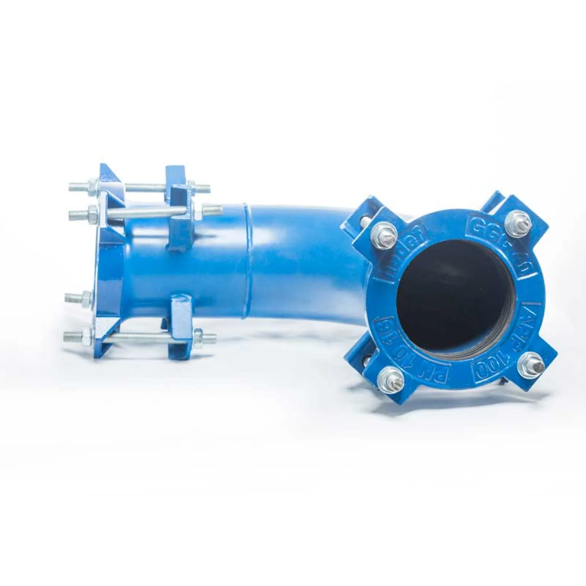
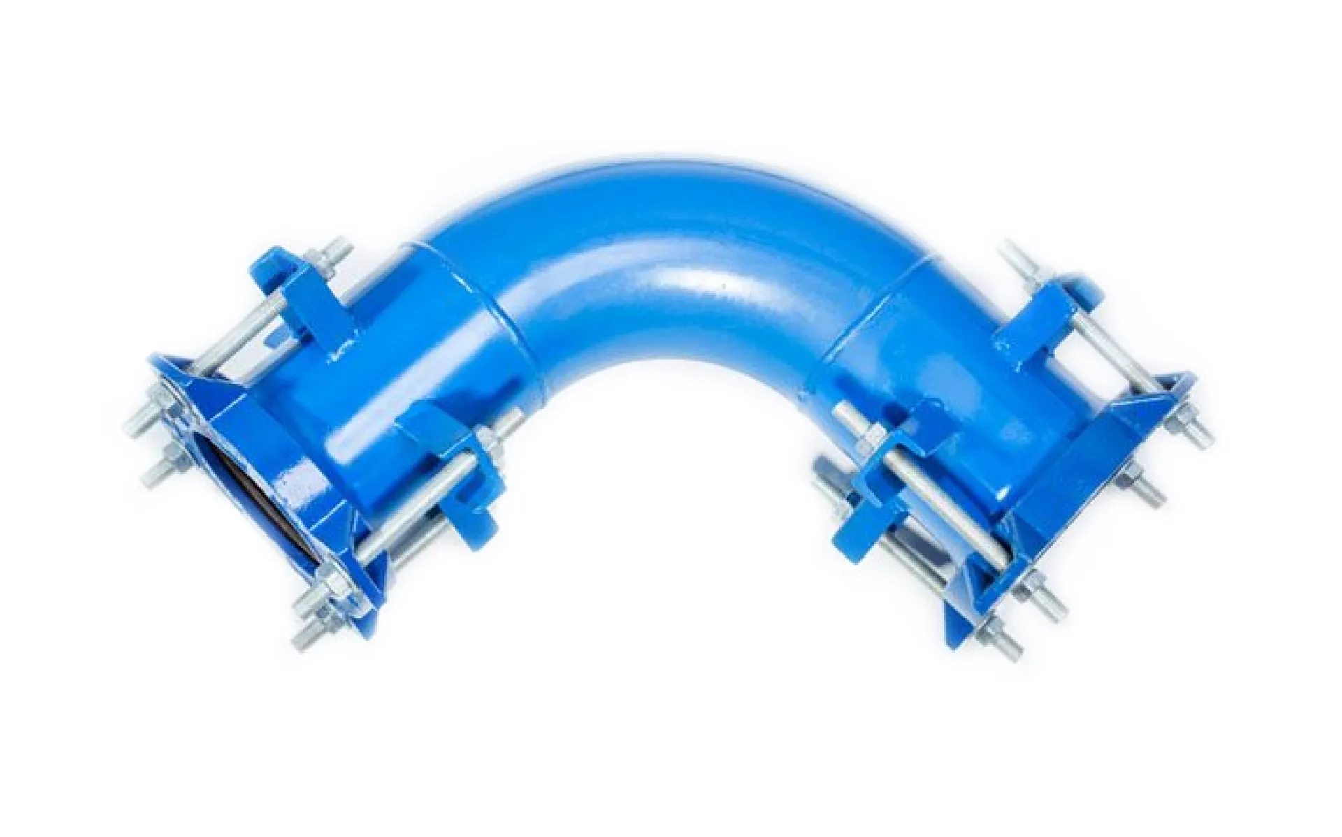
This instruction has been prepared for the safe and leak-tight installation of wide-tolerance APP Type Bends used to change the direction of pipelines made of different materials (Ductile iron, Cast iron, Steel, PVC, PE, GRP, AC, etc.) at the required angle.

  1. Pre-Installation Preparation
  • Product Check:
    Verify the label information on the elbow (DN size and tolerance range) and ensure it is suitable for the outer diameters of the pipes to be connected.
  • Angle Verification:
    Before installation, confirm that the elbow angle matches the required deflection angle of the pipeline.
  • Pipe Cutting:
    Cut the pipes perpendicular (approx. 90°) to the pipe axis. Uneven cuts may prevent proper seating of the sealing gasket.
  • Surface Cleaning:
    Clean rust, dirt, scale, and old coatings from the pipe ends using a wire brush.
    The surface in contact with the sealing gasket must be smooth and clean.
  • Chamfering (If Required):
    Apply an external chamfer of approximately 30° to the pipe ends if necessary.
    This prevents damage to the gasket during insertion.
  1. Positioning and Marking
  • Insertion Depth Marking:
    Measure how far the elbow will engage each pipe end and mark the insertion depth on the pipes.
    This ensures correct centering of the elbow.
  • Pipe Alignment:
    Position the pipes according to the required direction change.
    APP Type Elbows can typically accommodate up to ±6° angular deviation; however, alignment to the intended angle is recommended for optimal performance.
  1. Installation Steps
  • Lubrication:
    Apply a silicone-based lubricant suitable for potable water to the sealing gasket and pipe ends.
    (Do not use oil-based lubricants as they may damage the gasket.)
  • Placement:
    With the adaptor sections loosened, slide the elbow onto the first pipe.
    Bring the second pipe into position and insert it into the adaptor section up to the marked reference line.

If the elbow is a flanged type, ensure that the bolt holes are perfectly aligned with the mating flange.

  • Gap Control:
    Ensure a gap of at least 5–10 mm between the pipe ends and the end of the adaptor section to allow for thermal expansion and settlement.
  1. Tightening Procedure (Critical Step)
  • Cross Tightening:
    Tighten the bolts in a diagonal (crosswise) sequence (e.g., 12–6 o’clock, 3–9 o’clock).
    This ensures even load distribution on the gasket.
  • Gradual Tightening:
    First hand-tighten all bolts, then tighten gradually in multiple passes using a wrench.
  1. Final Check and Testing
  • Visual Inspection:
    Ensure that the gap between the pressure flanges and the adaptor body is uniform around the entire circumference.
  • Pressure Test:
    Perform a low-pressure leak test before commissioning the pipeline.
    If leakage is detected, recheck and retighten the bolts.
  1. Thrust Block (Anchorage) Requirement
  • If the elbow is not a pull-out resistant (restrained) type, internal pressure may cause displacement.
  • A concrete thrust block must be installed at the outer bend of the elbow to prevent movement.

SAFETY NOTES

  • Wear protective gloves and safety footwear during installation.
  • For large-diameter elbows, use pipe supports or blocking elements to prevent excessive load on the adaptor.
  • Ensure that the protective coating of bolts (galvanized, Dacromet, etc.) is not damaged to maintain corrosion resistance.

No

Component Name

Material and Technical Details

1

Adaptor Bend

ST 37 Steel. High-strength structural body

2

End Rings

Ductile Iron (GGG40/50) / ST 37 Steel. Pressure end caps applying force to the gasket.

3

Flange (Optional)

Zinc-Coated ST 37 Çelik. Compatible with various flange standards

4

Tee Bolts/Bolts

Zinc-Coated Grade 8.8 Steel / AISI 304 / 316 Stainless Steel. High corrosion resistance.

5

Conical Gasket

EPDM / NBR. Pressure-responsive sealing technology.

6

Nuts and Washers

Zinc-Coated Grade 8.8 Steel / AISI 304 / 316 Stainless Steel. Secure locking system.

7

Coating

Epoxy / Thermoplastic. Long-lasting protection and durability.

90°, 45°, 22,5° ve 11,25° 
Non-standard angle dimensions are also available
REFERENCE DIAMETER (mm) APP CODE COMPATIBLE PIPE TYPES (mm)
50 APP 50 50 Steel, 63 HDPE, 63 PVC
80 APP 80/1 80 AC (PN 10), 80 Steel, 90 PVC, 90 HDPE, 80 Ductile, 80 CI
APP 80/2 80 AC (PN 10), 110 PVC, 110 HDPE 
100 APP 100 110 PVC, 110 HDPE, 100 AC (PN 10), 100 CI, 100 Steel, 100 Ductile
125 APP 125 125 AC (PN 10), 140 PVC, 140 HDPE, 125 Steel, 125 CI, 125 Ductile
150 APP 150/1 160 PVC, 160 HDPE, 150 Steel
APP 150/2 160 PVC, 160 HDPE, 180 PVC, 180 HDPE, 150 Steel, 150 CI, 150 Ductile, 150 AC (PN 10),
APP 150/3 150 AC (PN 12,5), PN12,5, 200 HDPE, 200 PVC
175 APP 175 175 AC (PN 10), 200 Steel
200 APP 200/1 225 PVC, 225 HDPE, 200 Steel, 200 Ductile
APP 200/2 200 AC (PN10), 225 PVC, 225 HDPE, 200 Ductile, 200 CI
APP 200/3 200 AC, (PN 12,5) PN 12,5, 250 PVC, 250 HDPE
250 APP 250/1 250 Ductile, 250 Steel, 250 CI
APP 250/2 250 AC (PN 10), 280 PVC, 280 HDPE
APP 250/3 250 AC (PN 12,5)
300 APP 300/1 315 PVC, 315 HDPE, 300 CI, 300 Steel, 300 Ductile
APP 300/2 300 Ductile, 300 AC (PN 5)
APP 300/3 300 AC (PN 10), 355 PVC, 355 HDPE, 350 Steel
350 APP 350/1 300 AC (PN12,5), 350 Ductile, 350 CI, AC (PN 15)
APP 350/2 350 AC (PN 10), 400 PVC, 400 HDPE, 400 Steel
400 APP 400/1 400 Ductile, 400 CI, 400 GRP
APP 400/2 400 AC (PN 10), 450 PVC, 450 HDPE, 450 Steel
500 APP 500/1 500 Steel, 500 HDPE, 500 PVC, 450 AC (PN 10)
APP 500/2 500 Ductile, 500 CI, 500 GRP
APP 500/3 500 AC (PN 10), 560 PVC, 560 HDPE
600 APP 600/1 600 Steel, 500 AC (PN15)
APP 600/2 600 Ductile, 600 CI, 630 PVC, 630 HDPE, 600 GRP
APP 600/3 600 AC (PN 10), 600 AC (PN12,5)
700 APP 700 AC, Steel, Ductile, GRP, PE, CI
800 APP 800 AC, Steel, Ductile, GRP, PE, CI
900 APP 900 AC, Steel, Ductile, GRP, PE, CI
1000 APP 1000 AC, Steel, Ductile, GRP, PE, CI
1200 APP 1200 Steel, Ductile, GRP, PE
1400 APP 1400 Steel, Ductile, GRP, PE
1600 APP 1600 Steel, Ductile, GRP, PE
1600-3400 APP1600-3400 Steel, Ductile, GRP
Custom production is available for pipe diameters not listed.
up